Network diagrams that visualize your topology, both logical and physical, are key to effective network and IT infrastructure management. With up-to-date diagrams, network admins can troubleshoot (and minimize downtime), plan for capacity, avoid IT clutter, maintain software, and keep the network secure and compliant. There are two main types of network diagrams: physical and logical. Physical diagrams (which are common in DCIM software) depict the physical topology of the network and how the physical devices (or objects) are connected. In this post, we’ll take a look at what a logical network diagram is.
Logical Network Diagrams Explained
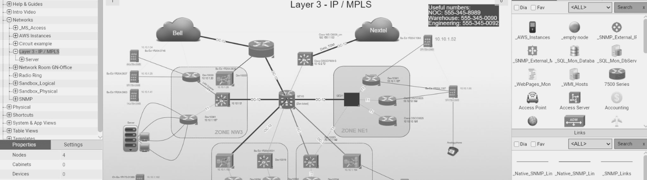
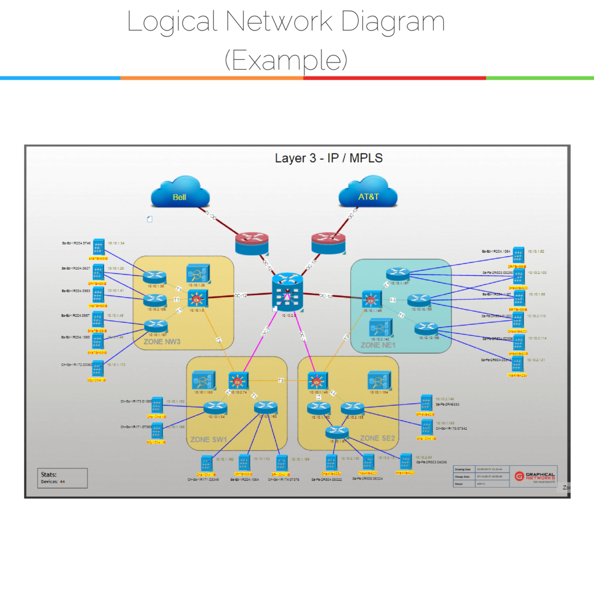
A logical network diagram depicts how information in the network flows. In a logical diagram, you’ll generally visualize the following elements in your logical network topology:
- subnets (such as: IP addresses, VLAN IDs, and subnet masks,)
- network objects (routers and firewalls)
- specific routing protocols
- routing domains
- voice gateways
- traffic flow
- network segments
How Logical Network Diagrams are Useful
As the information contained within logical network diagrams corresponds to the L3 (Layer 3) of the OSI model; L2 devices (such as switches) are not depicted in an L3 or logical network diagram. While physical network diagrams are important, logical diagrams make network management easier in the following ways:
- Troubleshooting.If service is out somewhere between two IP addresses, you can use a logical diagram to quickly rule out an issue caused by a firewall.
- Firewalls.With logical diagrams, you can ensure your firewall rules stay accurate.
- Eliminate redundancies.Logical network diagrams will clearly help you determine what isn’t redundant — and what is.
- Capacity planning.Although physical diagrams are instrumental in capacity planning, logical diagrams also help. With these topology diagrams, you can map out expanding or changing the network and see what will impact what.
- Sharing network information.If you need to share information about the logical network, but want to conceal physical information about the network, you should use a logical network diagram.
How to Create a Logical Network Diagram
As a logical or L3 network diagram should depict the logical network topology: in general, you’ll want to map out the following logical elements:
- VLAN IDs
- Subnets
- Names/Labels
- Network address and subnet mask
- L3 Devices such as routers, VPN devices, and firewalls
- Crucial servers (for example: DNS)
- IP -addresses
- Logical interfaces
- Routing protocols
Keep in mind that these diagrams are only as valuable to you as they are up-to-date. If your logical network is tiny, you may be able to create a logical network diagram by hand — or creating Visio network diagrams. If your network doesn’t fit in a shoebox, however, you will probably want to use some kind of automated network mapping software for your logical network (such as netTerrain).
To sum up, both logical and physical diagrams play a key part in effectively managing the network. If you aren’t documenting the network, or you’re scrambling to keep up using a hybrid of post-it notes, Visio, and Excel — you may want to look at a network mapping tool to help you automatically discover and map the network in clicks. Network documentation, when done properly, can deliver some serious ROI.
Further readings on logical diagrams and network documentation: