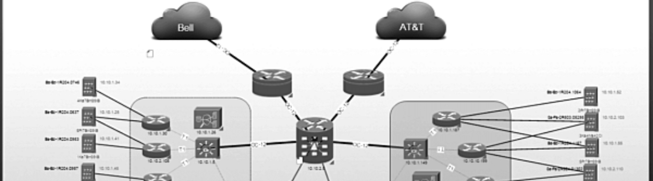
 Network diagrams are a visual tool that give network administrators a window into the network: they are used to visualize objects/nodes, connections, dependencies, critical paths, tasks, and more. Because networks are complex, there are different types of network diagrams to deliver various types of information.
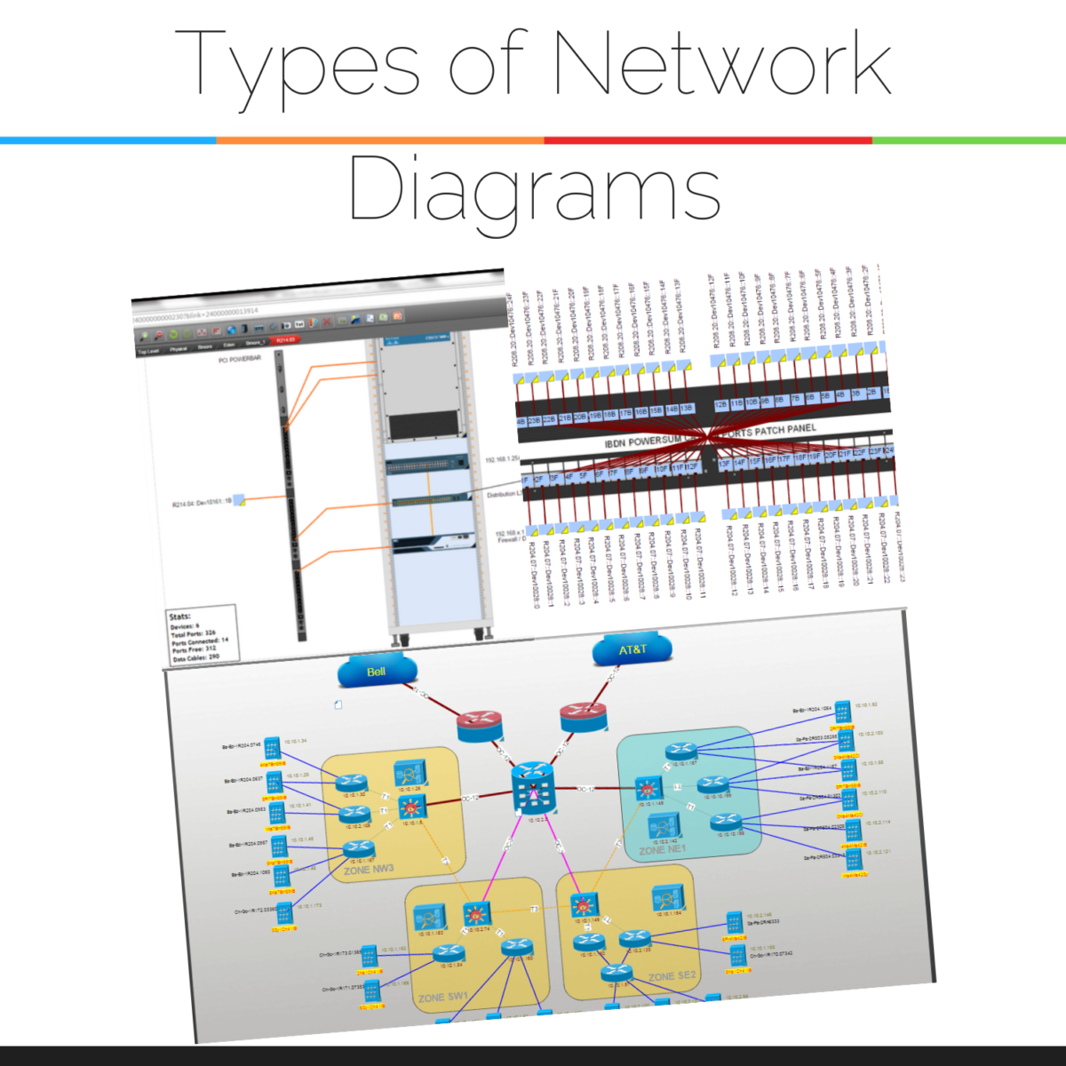
Step 1: Understand the Types of Network Diagrams
- basic network diagrams,
- physical network diagrams,
- logical network diagrams,
- hybrid (physical and logical) network diagrams,
- and 3D network diagrams.
Step 2: Discern the Purpose of Your Network Diagram
The main purpose network diagrams serve is to give insights about how the different components in a network work together. A secondary purpose of network diagrams, which is a natural result of being able to see how everything in the network works together, is to assist with troubleshooting. When you can see how everything works together, you can better pinpoint what needs to be remedied when something in the network is not working correctly.
Step 3: Decide What Level of Detail the Network Diagram Needs
Because a network diagram’s level of detail isn’t set in stone, what’s included in a network diagram depends upon what the organization (and the network) is and needs. For example, some organizations may have greater security needs — and the network will have more security components that need to be included in a diagram.
Commonly mapped elements in network diagrams include:
- All of the connections in the network — and leaving the network.
- All network devices and data (including routers, firewalls, switches, and so on)>
- Any wireless networks
- Modems
- Applications
- IP addresses
- VLANs that are currently being used
Ultimately, what a network administrator includes in a diagram will depend upon the purpose of the diagramming project, what is actually in the network — and how, exactly, the diagram is created…
Step 4: Ways to Draw Network Diagrams
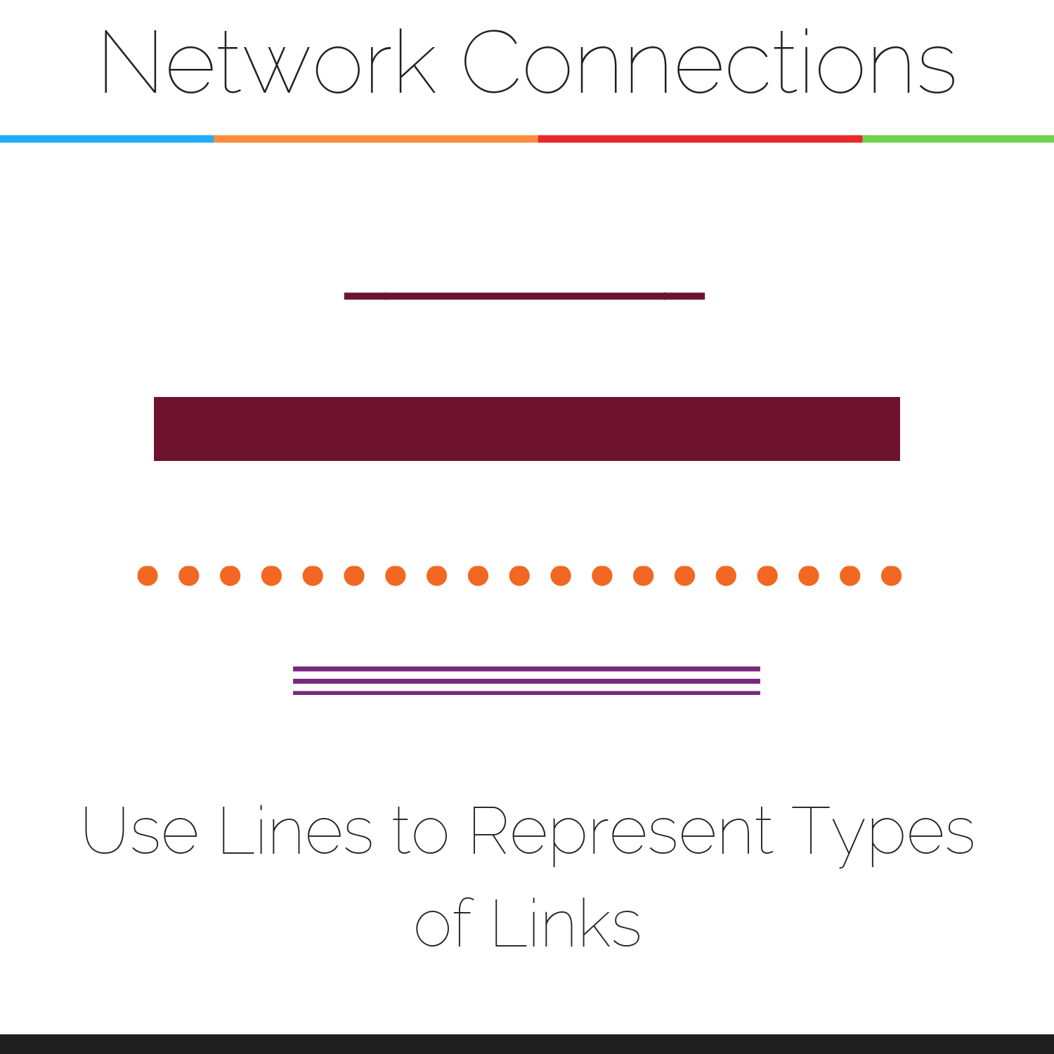
To create a network diagram, you’ll want to establish a hierarchy of levels (for example, do you have multiple buildings or just one?). Next, you’ll want to include the components for a given network — servers, routers, hubs, printers, and so on. Once you have mapped out your components on the diagram, you’ll want to connect them.
Use lines to depict connections between network components — you can use different types of lines (such as dotted or solid) and levels of thickness (thin and bold) to represent different types of connections.
Step 5: Methods for Creating Network Diagrams
Just as there are many types of network diagrams (such as logical and physical), there are a variety of different ways to create network diagrams. The number one difference between network diagrams is what you use to create them, which will be one of the two methods:
- Create network diagrams by hand
- Create network diagrams with software
Creating Network Diagrams by Hand
Theoretically, you can draw network diagrams by hand. How valuable, and how accurate, your hand-drawn network diagrams are will depend upon how large your network is vs. how much time you can devote to maintaining them.
Creating Network Diagrams with Software
A variety of different tools exist for creating network diagrams with help from computer automation. You can use spreadsheets, Visio, a combination, free network documentation tools, or an enterprise-grade network diagramming software such as netTerrain. Network diagram software is a good choice for mid to large networks — choose a software that is robust enough to help you keep up with all of the changes a network undergoes on a daily, weekly, and monthly basis.
Bottomline? As networks today continue to grow, the need to map and diagram them is also growing. We use maps throughout our lives — from finding a specific store at the mall to driving to a job interview to using a website: it only makes sense that if you are managing a network, you need a map to be able to find components, maintain them and troubleshoot problems as they arise.