
In the previous blog, we started digging a bit deeper into the details of OSP circuits in netTerrain. This blog is also very technical: we will analyze how netTerrain terminates and patches up the circuits paths that we designed previously.
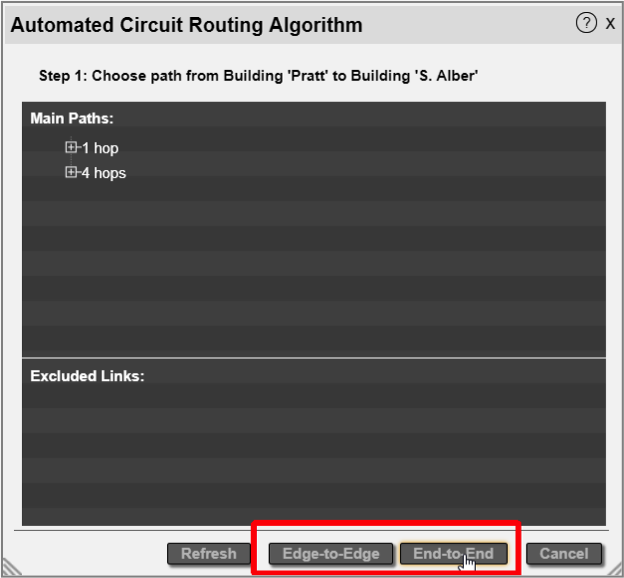
Once you have your paths — with the correct hops, cables and strands — you must decide how you terminate the circuit. More specifically, will it be an edge-to-edge or end-to-end circuit?
Since circuit paths utilize strands and patches (more on that later) to traverse the fiber network between points A and Z on the map, it is ultimately the devices (and a pair of ports on them) that provide the physical infrastructure for a circuit path to exist.
Edge-to-edge versus end-to-end circuits
For the intermediate nodes, we sometimes refer to the ‘fiber equipment’ as the hardware infrastructure that supports the paths. The purpose of the fiber equipment is to simply serve as transport for these circuits. This will become clear when we launch a circuit layout record.
We usually terminate the circuits in the A and Z locations on network equipment, not on fiber equipment. After all, the circuit should serve an actual purpose for some network end-user. In these cases, we refer to the circuit as ‘end-to-end’. More precisely, the circuit path is patched through fiber equipment in the intermediate nodes; on the A and Z locations, there is an extra patch between the terminating fiber equipment (edge) and the final end-user or network equipment ‘end’. For end-to-end circuits, the user also must choose which network equipment the circuit should terminate on for both locations.
In some cases, however, you may not know which end equipment the circuit will serve. If you still want to create the circuit (perhaps to make sure nobody else takes up those resources), you can still do it by creating an ‘edge-to-edge’ circuit.
 Selecting between an edge-to-edge and end-to-end circuit
If you choose an edge-to-edge circuit, netTerrain determines the endpoint fiber devices automatically. For an end-to-end circuit, netTerrain still selects the fiber devices on the A and Z locations, but you get to choose the end network equipment.
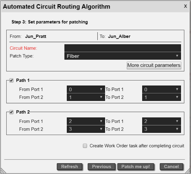
The final step of the circuit design process consists of selecting the end ports of the devices picked for the A and Z locations as well as entering any other parameters for the circuit.
 Choosing the circuit end ports and parameters
For each intermediate node along each path, we have a device where the strands for the entering hop connect to, and a device where the strands for the departing hop exit. netTerrain will patch these up automatically for your circuit, so it has fiber continuity.
As a final bonus, if you also want netTerrain to create a work order task for your circuit, you can do that too. And that’s it, phew!
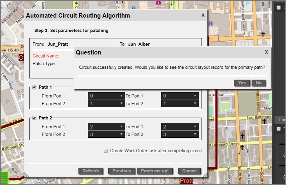 Circuit complete!
After the circuit is complete, you can see the result — graphically — in a so-called ‘circuit layout record’, which we will review in our next blog.
While this whole process seems quite elaborate at first, it is actually quite automated. netTerrain picks the optimal paths for you, selects default cables and strands, and even patches up the circuit along the way. Most of the explanations around this process deal with the details of how to override some of the decisions the software makes for you. Being as automated as it is, this process is prone to more automation through the API: you can have an external program send API calls to netTerrain via REST or SOAP and have the same circuit created 100% automatically (without any human intervention).
Going over the details of the API is a bit out of the scope here but, as always,
feel free to drop us a line, or if you are a customer, enter a portal ticket and we can give you some additional pointers concerning API automation and netTerrain.