
A circuit layout record (CLR) is an end-to-end view of a linear connection between two endpoints, on one page. We have seen these before, as when we launched a CLR for a cable or a port, netTerrain tries to follow the path as far out as possible until it encounters no more connections or too many (aka a split).
With circuits, however, we have a more granular definition of a CLR: a one-page view of one of the edge-to-edge or end-to-end paths a circuit takes. We even provide two flavors of that CLR: a block CLR and the traditional swimlane CLR.
Why a CLR?
Circuits in your fiber plant, as we have seen already, traverse from locations A to Z through intermediate nodes on a map. The underlying circuit infrastructure, however, is connected through strands and patches terminating on ports inside a card or device, mounted on a rack in a room, etc. As we can see, there is a whole hierarchy of sub-diagrams associated with each node. If we were to visualize the whole path of a circuit, we would have to start navigating netTerrain, clicking and then double-clicking on objects and, by the time we are done, we forgot where we started! Also…if you were to provide the information to a technician to configure the circuit in production, you would have to print a ton of diagrams and explain to that technician how netTerrain works. This is where the CLR comes in handy.
A CLR shows you all the information you need to know for the circuit, in one printable page and without the need to navigate an array of different diagrams.
The Block CLR
For both the ‘block’ and the ‘swimlane’ CLR views, we show you each hop and each node — along with some properties. The difference between the two types of CLR is in how we display these on the page. In the block CLR, each node down to the port is displayed as one simple block (hence the name). It’s important to note is that a CLR shows you one path at a time. Below is an example of a block CLR:
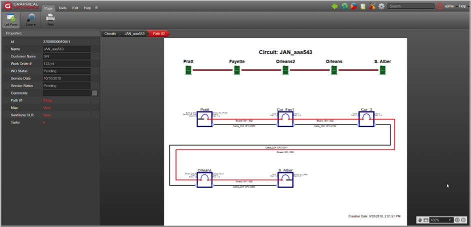 Block CLR for a secondary path
The block CLR shows two graphics: a top graphic representing the map-level path the circuit path takes and a bottom graphic showing the entire hierarchy for each node as text displayed next to the block representing that node hierarchy. It’s easy to see why a block CLR is convenient: by looping around the page it can accommodate many hops.
Here is a detail of one of the nodes:
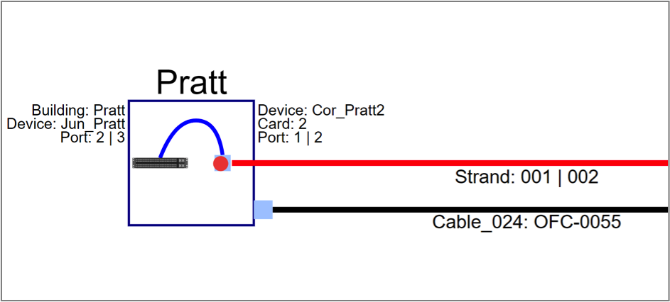 Node detail on the block CLR
The block includes a representation of the port where the strands and patches are connected and the cable that contains the strands. It also shows both port and strand numbers for each of the strands on the pair.
The block CLR properties window shows the name and custom fields of the circuit, along with a link to see the main or secondary path (if it exists), a link to show you the circuit path on the map, and a link to open the swimlane view of the path:
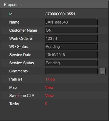 CLR properties window
The Swimlane CLR
The swimlane CLR is somewhat similar to the Bloc except that it shows the entire hierarchy for each node and it does not loop around the diagram in the presence of many nodes as it just keeps drawing the path horizontally. This makes it less convenient for printing if the paths are long.
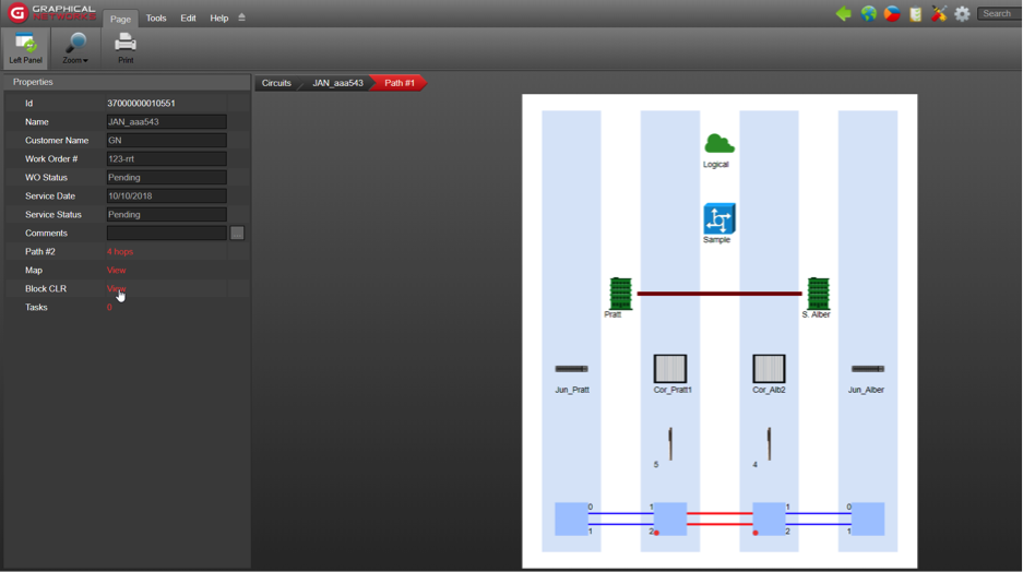 Swimlane CLR
From the swimlane CLR properties, you can also access the alternate CLR paths, the map representation of the path, and the block CLR view.
In the next blog, we’ll look at something quite important in fiber plant circuit design: the creation of redundant and diverse paths.