When it comes to doing less manual work, automation and discovery are great: just bring in devices, links, ports, and more into netTerrain and let the machine do the work. We’ve talked about this in great detail in previous blogs — and about how you can automatically position of the objects that you import automatically: with commands, via the API and more.
There are, however, cases in which you can’t completely automate the look and feel of your
network diagrams. Part of it is that, too often, a machine simply cannot figure out the meaning of “pretty”. In other cases, you need to enhance the diagram with elements that are simply outside the scope of what can be automatically figured out. This could be: free text, a background image or other decorative elements — such as bend points on links.
netTerrain offers an array of features, aka a bag of tricks, that while still being done by a human, can dramatically speed up the process of improving the aesthetics or enhance your diagrams beyond what any automated process can do.
In this blog, we’ll go over fast arrangement and alignment methods you can use to quickly improve the layout of your nodes and links on a page. In many cases, users need to arrange multiple objects in a row, column, or rectangle. Users may also need to resize a set of objects. As a faster alternative to individual arranging and resizing, netTerrain offers two convenient menu options:
Fast node arrangement
The ‘arrange’ button lets users arrange a set of objects in a row, column, tile or ellipse as well as left, right, top and bottom alignment. An additional graph layout algorithm called ‘Force directed layout’ helps a user spread out connected nodes to minimize crossings. Users select the objects that need to be arranged using the selection button and then proceed to select the best suitable arrange option.
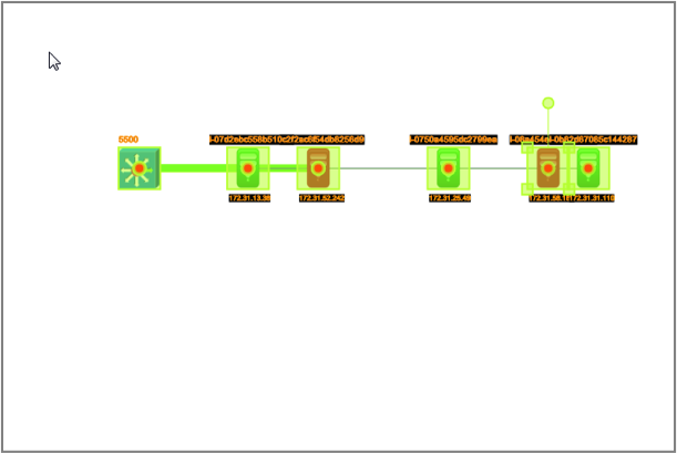
Row and column arrangement provide options to arrange a bunch of nodes in a nice tidy row or column. Just select a set of objects and click on the ‘arrange’ button and select the arrangement type (for example row). Additional options to make that arrangement smarter include the order in which you arrange the nodes, the spacing method, and how you want them centered:
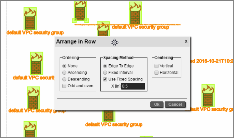 Arranging a set of objects in a row
Tile arrangements let the user create “object matrixes” with predefined row and column dimensions. In addition to the options above, tile arrangement also provides the option of selecting the number of rows or columns for the object matrix.
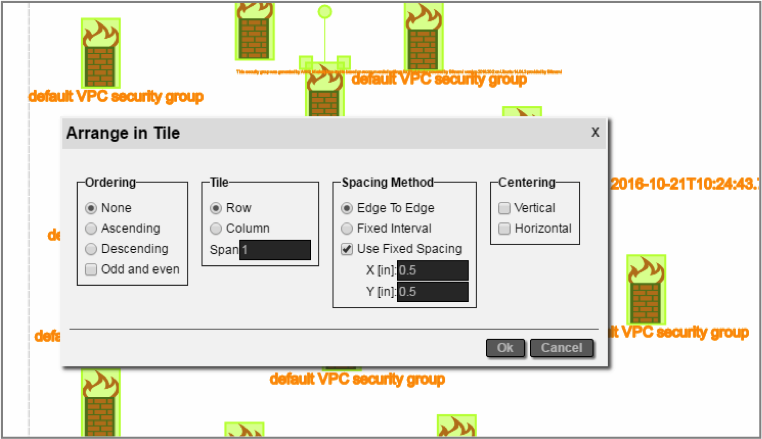 Arranging a set of objects in tile
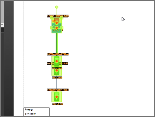
The ellipse arrangement option provides a convenient way to arrange objects in, you guessed it, an ellipse (as shown in the diagram below). The ellipse layout can arrange objects in two ellipse ‘layers’, where the internal layer is comprised of a set of objects of a certain type and the external ellipse of all the other objects connected to the first layer. Ordering of objects, separation between ellipses, and the height and width of the internal ellipse — as well as the centering of the resulting ellipse with respect to the page are the other options for this algorithm.
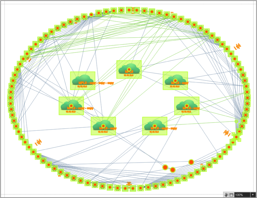 Object distribution after applying ellipse layout
In some cases, you may want to have a large set of nodes and links automatically dispersed within a diagram. For instance, when you perform a discovery operation and a large set of devices and links are automatically added within a diagram, they are usually cobbled together in a bundle of nodes and links on the top left corner of the diagram. It can be very time-consuming to try and place these nodes and links manually. With the ‘force-directed layout’ algorithm you can spread out nodes and links and minimize link crossings for improved diagram readability.
The algorithm includes a setting referred to as the ‘energy level’. Low energy level values translate into less link crossings…but also into higher processing times for running the algorithm. The energy level value can be set between .01 and 1. (science-fiction-y stuff but useful).
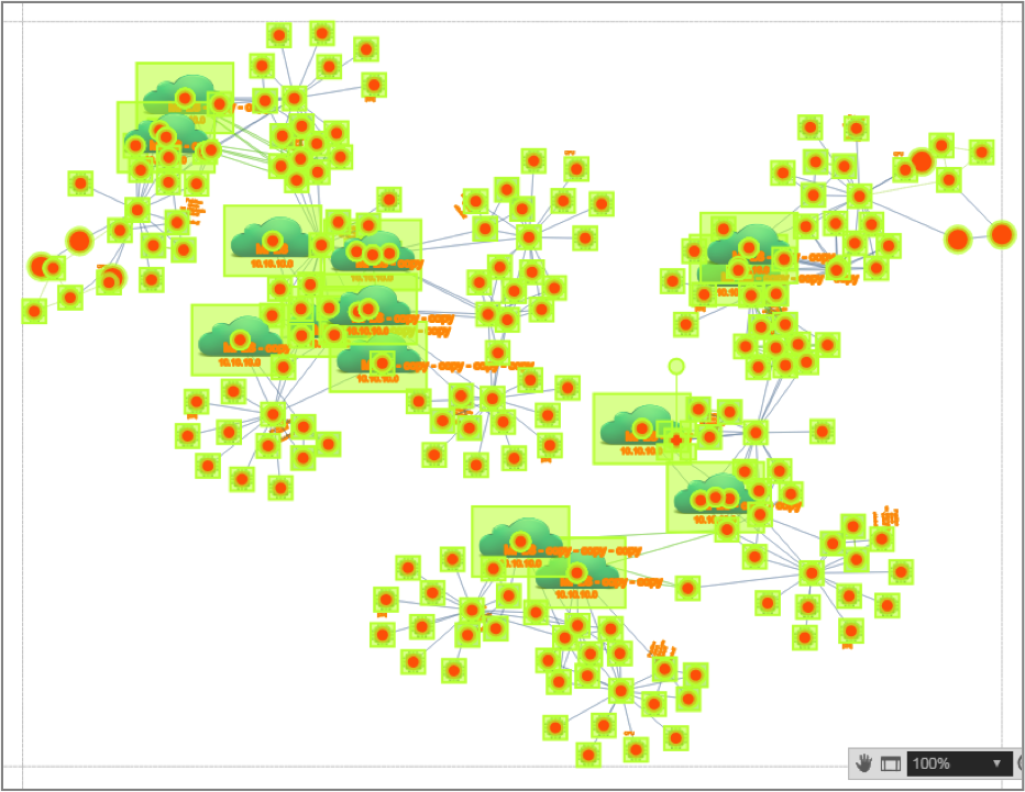 Diagram after the ‘Force directed layout’ was applied
A final tip in this blog relates to alignments for nodes. In many cases, users want objects on a diagram to be aligned in one dimension, while maintaining the same relative position in the other dimension. For this purpose, netTerrain has the option to align objects based on the left-most, right-most, top-most or bottom-most object in the selection.
Below, we show some screenshots after a left and a top alignment operation:
 Objects after a left alignment operation
 Objects after a top alignment operation