
Welcome back. In the previous blog, we drilled into some of the uses for device cards for your network documentation or Data Center Infrastructure initiatives. In this blog, we will go over the actual modeling process of cards in the catalog. We try to keep our blogs vendor-neutral — however, here we are talking about a process that most DCIM software packages or network mapping tools simply don’t even have, so it’ll mainly focus on our DCIM software (netTerrain).
Card modeling basics
A card is modeled in the catalog pretty much in the same way a device is modeled.
Step 1: the basic stuff
You start with the very basic stuff first: a model name, a front view image and some additional settings. It gets meatier after.
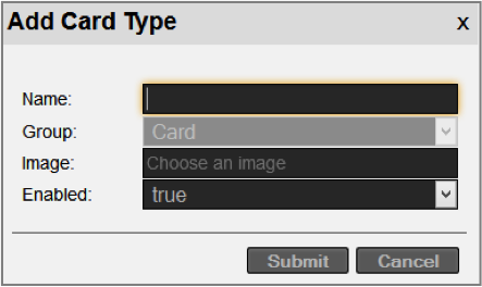 Adding card types in the catalog
Step 2: properties and rules
The next step is usually the assignment of properties and rules. In the previous blog, we talked about predefined fields that exist for cards. However, in netTerrain you can also add as many custom fields as possible, on a per card type basis. This gives you maximum granularity when it comes to recording important properties for these objects. Any property for the card can also have rules (or so-called visual overrides) that can control the look and feel of a card based on changes in any property.
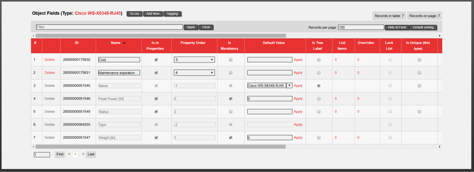 Card properties
Card fields can have all sorts of settings: the order in which they appear in the properties window, whether they are mandatory or not, default values, list items and visual overrides, whether values need to be unique, whether they are displayed on the actual diagram or not and if so, what font type, color, size and so on these properties use. And the best part: you can control that yourself from a simple GUI, in a few clicks, down to the ‘T’ and for every property! Talk about a DCIM tool being flexible…
Step 3: card backplane modeling
After you are done with the properties and the rules, you’ll proceed with the central part of the modeling — which is the backplane view of the card with its ports and other subcomponents.
The card modeling process consists of the following sub-steps:
- Assigning basic physical properties
- Adding a background image
- Modeling Ports (and maybe other slots, if it is a nested hardware type)
- Making it all look very pretty!
The physical properties are not the custom fields we mentioned above as instead they deal with the actual physical aspects of the hardware: size, weight, nameplate power and so on.
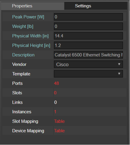 Physical properties of cards
A card background image is usually necessary to aid you in the process of laying out the ports on top of it nicely. It also gives the card model a realistic view.
Then you add the ports. This is done easily — with the click of a few buttons — in the netTerrain catalog modeler.
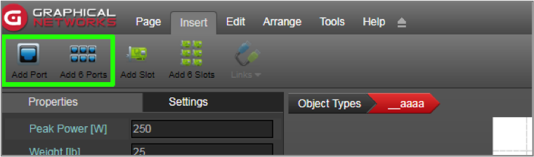 Buttons to add ports in card model
Each port is an object in its own right. As such, when these ports are automatically created in the project, they will inherit default properties from the modeler: name, protocol and connector. In addition, each port can also have custom properties with rules and default values and all that nice stuff.
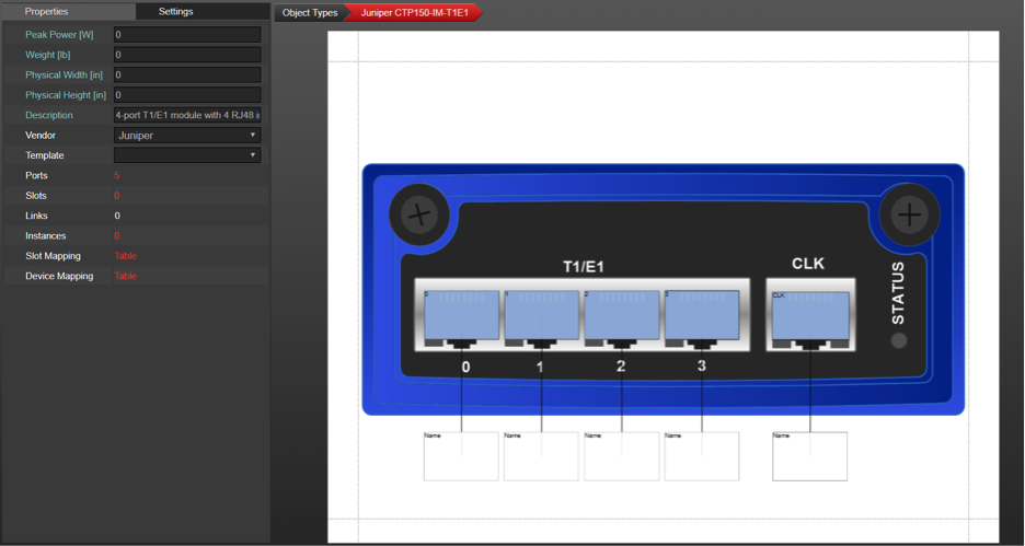 Port modeled on top of a card backplane
Finally, you’ll make it all look pretty by moving and resizing the ports on top of the backplane. netTerrain has countless shortcuts, buttons and tricks to make this process smooth: array and resize in bulk, copy formats and much more, so that if you have, say, 48 ports, you don’t have to move and resize each one individually.
A really cool feature of the aesthetics of netTerrain and the modeler is that you can even control what ‘reference ports’ look like and where they are positioned by default. A ‘reference port’ is basically a pictorial representation of the connection on the other end (once you start connecting these ports with patch panels and so on). Because, you know, netTerrain supports in-diagram links, as opposed to virtually every other DCIM tool that doesn’t .
Finally, because ports can have an unlimited number of custom fields, and you can choose which ones will be displayed on the diagram by default you may want to control the aesthetics of that too. Port and reference port displayed fields can also be set in advance in the modeler so that they follow a predefined pattern for each instance in the project. This saves time when creating nice looking card diagrams.
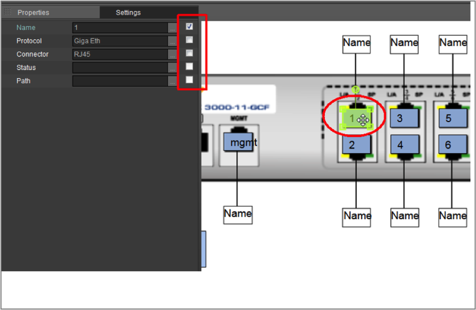 Port displayed field selection