Here’s another post in our series – Adventures in Network Documentation. Wouldn’t it be easy if all of your stakeholders only needed to see the same view of your networks? It would also be great if we all had five day weekends and free ice cream for all…dream on, right? The reality is that, in many situations that may arise, different groups require access to views of your network from slightly different angles. So, what happens when you have a device that a certain group wants to see in a physical view while a different group needs to access it in a logical view?

We’ll look at an example of just how network documentation software can assist you in rendering different views of your network for different groups. Say, for example, that you have some users who are only interested in the physical representation of your network (such as rack elevation views or a tabling view) while other users exclusively need a logical view (such as an L2 or L3). You can provide these groups with their different views – without duplicating your efforts (and entering information twice).
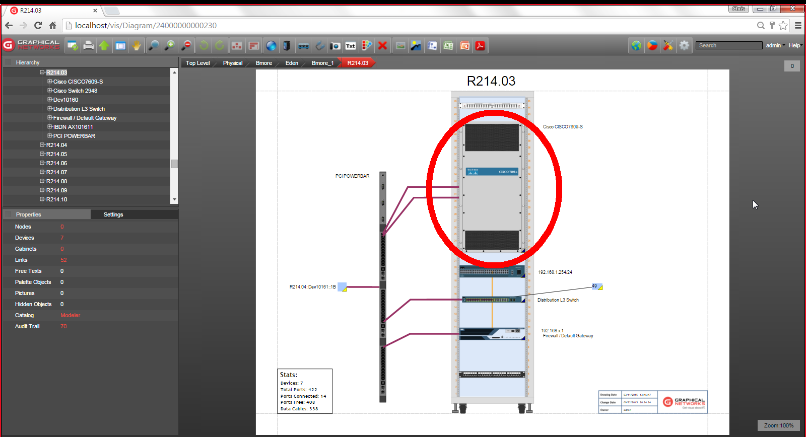
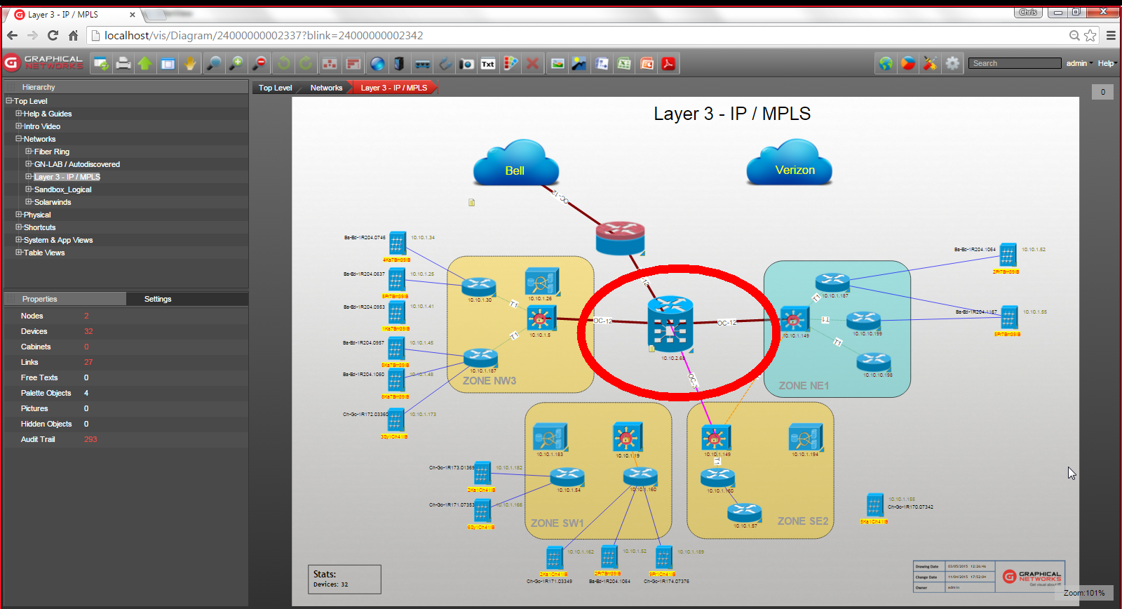
To demonstrate how you can do this with network documentation software, we’ll start in the physical view. If you have a switch that you want to put it into your L3 (logical) view, what’s the best way to do this? Well, you could copy it from your physical view and then go into your layer 3 view and paste the switch. Problem solved, right? Not so fast.

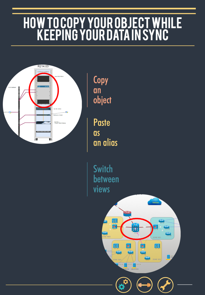
When you just copy and then paste, the objects may start with the same data, but they can get out of sync. If later somebody changes the data for the device in one way, it does not change in the other. A better way to do this is by means of so-called aliases. An alias is a mirror of the original object that always keeps the properties in sync with the master object.
In netTerrain, for example, you can copy the physical representation of a device and paste it as an alias in a logical view. If later the IP address changes in one of the views, it automatically changes in the other.
You may want to assign different icons to the same object, depending upon the view with which you are accessing the object. The ability to do this would depend upon which network documentation software you use, but if you are currently looking for a software, it’s a feature to consider. In netTerrain, for example, you can create a rule that assigns icons based on the type of object.

Having different aliases of the same object helps you create appropriate connections depending upon the layer with which you are viewing your object. For example, if you are in a logical diagram, you can create and view a logical type connection. For the same object, when you are in your physical view, you can forge a power connection between a switch and a fuse panel. Once you switch to your logical view of the object, you’ll be able to view the logical connection you created.
To sum up, when you need to show the same object in different views for different stakeholders or projects (or simply need to show info from a slightly different angle), you can do this using aliases. Using aliases ensures you don’t waste time typing in the same information for the same object just to be able to view it in a different layer.
Further, your connections should display appropriately: in the physical view, you’ll view cabling and physical connections while in the logical view, you’ll view logical connections. Some of the benefits of network documentation software depend upon how much you leverage the features that come with it. When you purchase your software, invest the time to learn how to best maximize its features.
