In this article and video, the third segment in our series on managing your outside plant with dynamic maps, you will learn how to apply netTerrain OSP to a very common scenario in GPON network mapping and fiber documentation: creating fiber strands and mapping them to a duct (you can click here to watch the accompanying video at any time).
To recap what you’ve learned in the series up to this point, we’ve
- created a map,
- and placed manholes within it.
With the manholes, we:
- named them,
- added some splice boxes inside of them,
- connected the manholes with a conduit,
- and we also created a bunch of ducts between the splices inside the manholes.
Mapping Fiber in Splice Boxes: Introduction
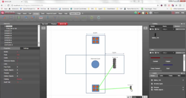
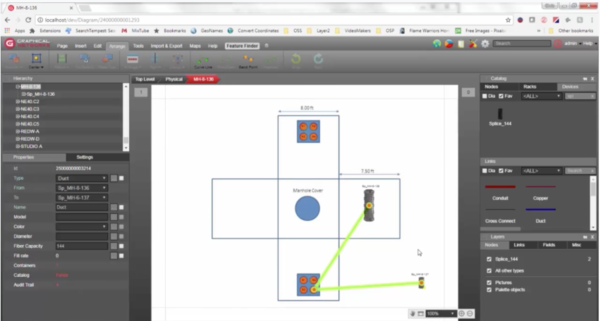
In the example we’ll be working on here, you’ll learn to map the fiber strands we create directly to the duct — this is to keep things simple, although, as a general rule, you’ll probably have a buffer in between. Similar to the example we used in segment #2, we have a conduit which has one duct inside (note that this is considered a ‘bundled’ link in netTerrain). Double-click on one of the manholes: you can see that we have a splice box that goes through one of the duct connection points — and then out to the splice which is inside the manhole located southeast of this manhole.
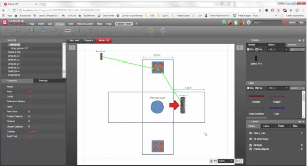
Need to go to the other manhole? Double-click on this splice box (which serves as the reference point here) to do so: if you go up, it shows up here on the manhole. You can see exactly how this happens in the video at 2:00 minutes in.
Working with Fiber Strands & Splice Boxes
Before we dive into working with fiber strands, we’ll take a look at the actual splice boxes. Inside of this manhole, you can find our splice. The splice you see here is just one way you can depict a splice box in netTerrain: you can have different types of splice boxes and we can model them in our catalog for you (as part of your maintenance, you can always request custom models from us — just request a model and we’ll get it back to you within 24-48 hours).
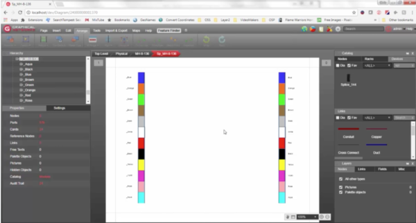
In this example, our buffers will follow the standard color coding:
- Blue
- Orange
- Green
- Brown
- Gray
- White
- Red
- Black
- Yellow
- Violet
- Rose
- Aqua
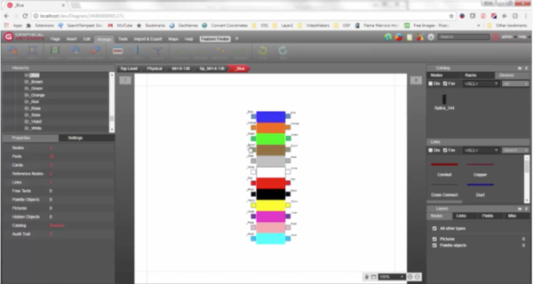
To see each of the fiber connection points for a buffer, just double-click it: the fiber strands will be connected to these connection points (which are treated as ports in netTerrain). In the video, you can see this happen (hint: skip ahead to 2:56).
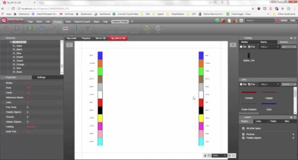
We have 12 buffers here: if you go up, you have 12 that go in and 12 that out for the splice box. This setup is based on how it is in real-life: you’ll have the fiber coming from the left and it’s cross-connected to the right. A note about colors: there is no hard-and-fast rule that dictates the same color code be used in cross connections. You can, for example, have the blue and orange cross-connected to the green and yellow.
This is a good place to pause and illustrate just why hierarchies are so important to the success of your work: depending on what you do, the colors won’t always perfectly match up and having your fiber in a hierarchy — inside the splice box and using these buffers — makes life easier. Simply drill down on one of the buffers, select your connection points, and cross-connect them to the other end using the color codes.
Creating Fiber Strands
Next, we’ll create 12 fiber strands.
One method you can use to create your fiber strands is to click on a duct: inside it, you can see we have here connects two splice boxes. To create your 12 fiber strand, start by bringing up the netTerrain Cable Mapper as you can insert cables here (4:15 in the video).
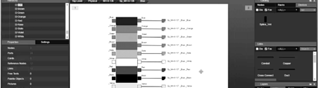
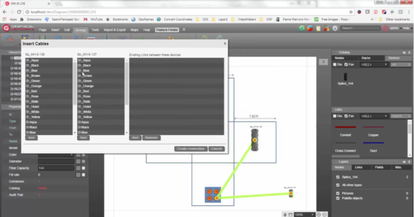
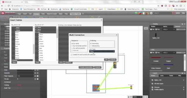
Above you can see the cable mapper’s intercable dialog box: in the left column, you can see one splice box ‘MH-8-136’, and, on the right, one splice ‘MH-6-137’. Within each column, every buffer is listed – both on the left side, and on the right side.
In the column representing the ‘MH-8-136’ splice box you can see that every buffer on the left side is marked with an underscore while the buffers on the right don’t have an underscore: look at ‘MH-6-137’ and you can see it follows the same structure. The use of the underscore here is just a personal notation I’ve chosen to use in order to differentiate the two sides — and to keep it sorted nicely (and simply).
In general, what you’ll want to do is to create 12 fiber strands that connect an outgoing part of a buffer on this splice box and connect it to 12 connection points, on this device, on the incoming side. Again, as with most things in netTerrain, there isn’t a hard-and-fast rule as to how things should be done: there are a myriad of ways to create these connections and you can change the notation — this example is just what works for me and how I’ve seen it done in many other instances. It’s simple because you’ve got the standard notation with the colors there so you can then simply expand.
To keep things simple, let’s connect blue with blue (you can see how this in action beginning at 6:10 in video). You can connect all of the outgoing fiber strands on the outgoing buffer on my local splice box to the incoming strands on the incoming buffer on my remote splice box: it simply multi-selects.
It’s easiest to pick the same sequence of colors: here, we’ll have ‘blue aqua’ with ‘blue black’, for example. Again, you don’t have to do it that way — you can pick any color you’d like. For example, you can pick ‘slate aqua’ with the ‘black brown’ and create the connection. Bottomline? Cross-connect any which way you need to.
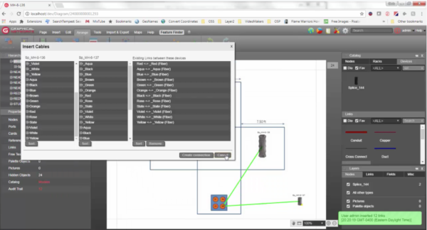
Create a Cable Hierarchy
Ready to create a cable hierarchy? We’ll use the blue, click ‘create connection’, select ‘fiber’ ( this is the link type we will use here — you can create your own cable type in netTerrain), I’m going to check this box to bundle “create link and bundle with selected”: the 12 strands i’m going to create with the duct itself. You’ve now created your cable hierarchy.
So: we now have the red with red and aqua with aqua and so on. If I click on the duct (the video at 7:34), we can see that we now have 12 bundled links (this shows in the properties bar on the lower left of the screen).
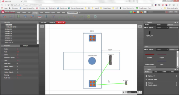
In the properties bar, you can also check out the fiber capacity for the duct: in this example, fiber capacity is set at 144. In this example, I’ve set a visual override that changes the color of the duct based on the fill rate (7:50 in the video) — this works the same way as we did with the conduits in the last post: it’s based on how many fiber strands you have. As you can see in the properties bar, the fill rate here is still at 8%, which is very low.
Putting It All Together
Curious to see how all of our work looks in the splice box now? (8:15 in video) Here’s how you can see these changes: navigate to the local splice box, filter the fiber out (layers > links on the lower right side) , and go to the blue buffer.
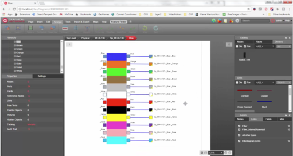
You can see inside your buffer that the blue is connected, remotely, to the blue on the other splice box. You can see that the blue buffer is connected to the blue fiber, the orange fiber in our blue buffer is connected to the blue buffer on the other end and the orange fiber — you get the idea.
In sum, we just created 12 fiber strands in netTerrain’s outside plant management software. As you can see, it’s a very easy process: these are automatically bundled with the duct simply by selecting the duct and bringing up the insert cable dialogue box, aka the Cable Mapper in netTerrain.
Coming up in the next segment of this series, we’ll show you how, once you’ve got all this fiber set up, you can trace specific fiber strands end-to-end. We’ll be looking at examples of circuit layout records.