In this final blog for our ‘Pretty Network Diagram’ series, we’ll focus on links. In netTerrain, links are not just black lines connecting two nodes: they can have styles, colors, thicknesses, can include bend points, and can also be arranged nicely when you have several links connecting the same endpoints.
Link styles
Links can include different line styles, colors and thicknesses, depending on the link type that was defined when creating the instance. These styles are applied for all instances of a given link type, but can be overridden on a per instance basis, using visual overrides. The netTerrain catalog supports the following line styles:
- Solid
- Dash
- Dot
- Dash-dot
- Dash-dash-dot
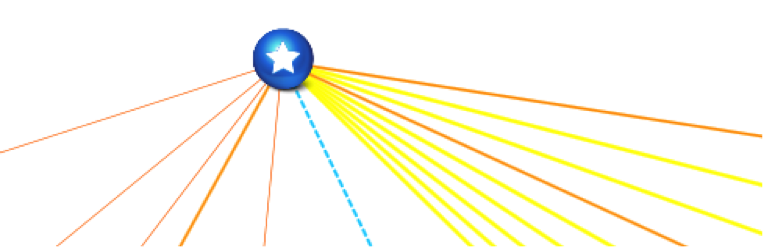 Links displaying different line styles and colors
Not only are these styles useful for aesthetic purposes, but they can actually convey a lot of information. As we have covered in a blog regarding visual overrides, a link with a certain thickness or color can communicate to the user that the link is carrying more bandwidth or is in a certain status.
Bend points
Bend points in netTerrain provide the ability to reroute links within a given diagram. A bend point will partition a link into multiple segments, but they all represent the same original link. By clicking on any segment, the properties for the link will be displayed.
To create a new bend point, select the link and click on the ‘add bend point’ button (‘b’ hotkey). Alternatively, you can create a bend point using the bend point button from the ‘arrange’ menu.
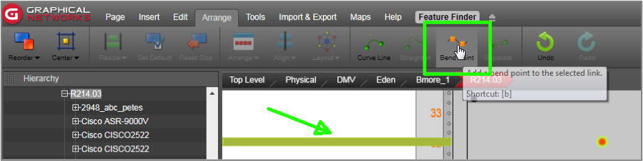 Adding a bend point
To create right-angled bend points, select the bend point and click on the ‘set right angle’ button (or alt-b). Once the right-angle button has been pressed, the bend point will be positioned at a right angle with respect to its adjacent nodes. The engine automatically determines what the best right-angle option is, based on the relative position of the bend point with respect to its adjacent nodes.
The general rule for this operation is that if the x coordinate of the bend point is closer to the right-most adjacent node, it will be located on the upper right corner of an imaginary right-angled triangle defined by the bend point and its two adjacent nodes.
To delete a bend point, simply select it and click on the delete button or key.
A very quick way of adding multiple bend points and directing the path of the link is to use the ‘b’ shortcut. Select the link of interest first and then press and hold ‘b’. Move your mouse to the position of where you want to add a bend point and press the left mouse button. This will add the bend point where you click on the screen. You can perform this operation as many times as you want in succession.
Often, you may find yourself wanting to create right angled paths for a link between two nodes. For example, you may want to lay out a link so that it looks like a right-angled U. Doing it all manually would require creating two bend points, then moving them appropriately to create a right angle. A much easier way to accomplish this is by using the link ‘right angle’ handle, as shown below:
 Using the right-angle handle
Just click on the link and then drag that handle until you create the desired U-shape. This feature can be used as many times as needed on any segment of the same link.
Separating links
In many instances, two nodes can be connected by several links which, by default, would be displayed on top of each other. For each link to be clearly visible, users can quickly accomplish the task of separating the links by selecting them and applying a link separation algorithm.
The process works as follows:
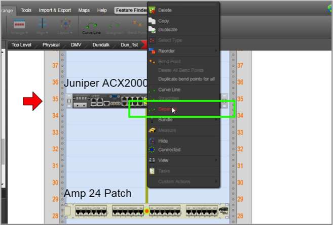
- Select the links (remember that they must start and end on the same pair of nodes). Also, note that since most likely the links will be on top of each other, you may have to select them using a selection box that crosses them at some point.
- Once the links are highlighted, right-click on any of them and click on ‘separate links’ or click on the ‘Separate’ button in the Arrange menu. Note that if that option is not enabled, you may have only selected one link. Make sure you have more than one link selected, and the endpoints are the same.
- With the ‘Separate Links’ dialog open, you can now choose from the following parameters:
a. Separation distance between links (in inches)
b. Number of bend points you want to apply to each link
c. Line curving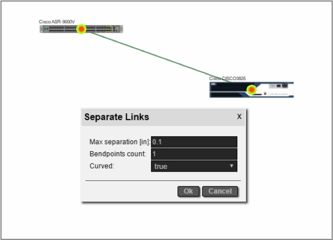
Note that this separation algorithm can be applied to any set of links sharing endpoints, regardless of bend point count, distance between links or curving state.
In sum, take advantage of the many features to change styles, add bend points and separate links to enhance your overall diagram look and feel and improve the information content of your network diagrams.