Up until now, links in netTerrain have been quite simplistic in terms of how they are modeled: just choose a look and feel for the link, assign some properties and, if needed, apply some rules (visual overrides) to some of those properties.
This works well for virtually all network mapping and most Data Center Infrastructure Management (DCIM) scenarios. In outside plant (OSP) applications, however, much of the work with links deals with fiber cables, which contain so-called ‘strands’. Due to the high number of strands that can exist in a fiber plant project, and the fact that the strands count is predetermined based on the type of cable (as we will see later on), a different approach is needed.
In this blog, we will look at how to model cables and strands in more efficient ways. We will refer to cables as ‘containers of fiber strands’ — although a cable in netTerrain is still, essentially, a link. In this sense, ‘link’ and ‘cable’ are used interchangeably.
Fiber cable and strand types
Before we dig deeper into how netTerrain models cables, let’s review some of the basics of fiber optic cabling. An optical fiber cable is an assembly containing one or more small optical fiber strands that transmit information by means of light signals with certain wavelengths.
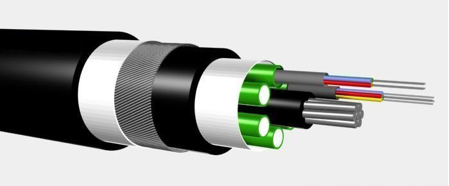 Multi-fiber cable representation
A fiber cable usually has a series of layers for protection and improved performance, with the strands being inside of the cable (and sometimes also organized in ribbons). There are myriad different strand counts available on the market (from a couple of strands per cable to up to a 864-count, consisting of 36 ribbons containing 24 strands of fiber each): some of the most common strand counts are 12, 24, 72 or 144.
When adding a cable in a fiber plant project in netTerrain, a user would ideally have these strands created automatically. When it comes to hardware, you already see this type of automatic creation of subcomponents: in netTerrain, a device may already have a predefined number of slots and a card and a predefined number of ports. Likewise, a power user can create a link type in netTerrain that is configured as containing strands, as depicted in the image below.
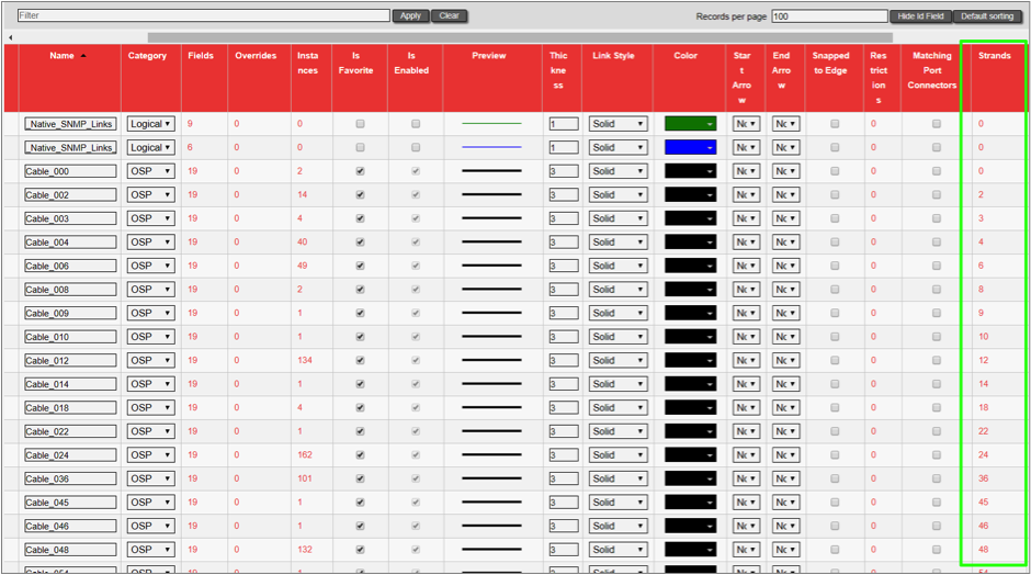 List of cables and their number of predefined strands
As an end-user, you can take one of the cables defined in the catalog as containing strands, apply them to your project, and they will automatically create these strands for you.
For high strand counts, or for cables with bundles (aka buffers) of 12 strands, it is common to identify each strand with a color code standard adopted from the early TIA telephone standards for copper wire, as shown in the table below:
| Fiber Number | Color |
|---|---|
| 1 | Blue |
| 2 | Orange |
| 3 | Green |
| 4 | Brown |
| 5 | Slate |
| 6 | White |
| 7 | Red |
| 8 | Black |
| 9 | Yellow |
| 10 | Violet |
| 11 | Rose |
| 12 | Aqua |
While cables are essentially just links in the netTerrain catalog (with some extra sizzle), strands in netTerrain are not truly links. You don’t see them graphically, and they are not individually modeled in the catalog. As we do with ports (where there is only one system type called ‘port’), in the netTerrain catalog there is a system type called ‘strand’. A power user can assign custom fields to the strand system type.
Managing strands
Adding a cable with strands to your fiber plant diagram is similar to adding any regular link. For example, you can drag and drop it from the catalog into the project by connecting it to the endpoints.
Once created, the cable will list all of its strands in the properties window as a clickable hyperlink:
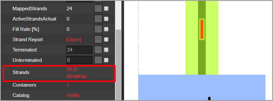 Strands displayed in the cable properties window
The clickable ‘strands’ hyperlink opens a new list view from which you can manage the strands. This list view includes a number of features to help you manage strand usage, attributes and capacity.
Each strand name inherits the predefined name, for the strand assigned, for that cable type in the catalog.
From the list view, you can also:
- exclude certain strands for circuit usage (more on that later),
- manage the strand endpoints,
- change the strand status,
- or fill out any strand custom field data.
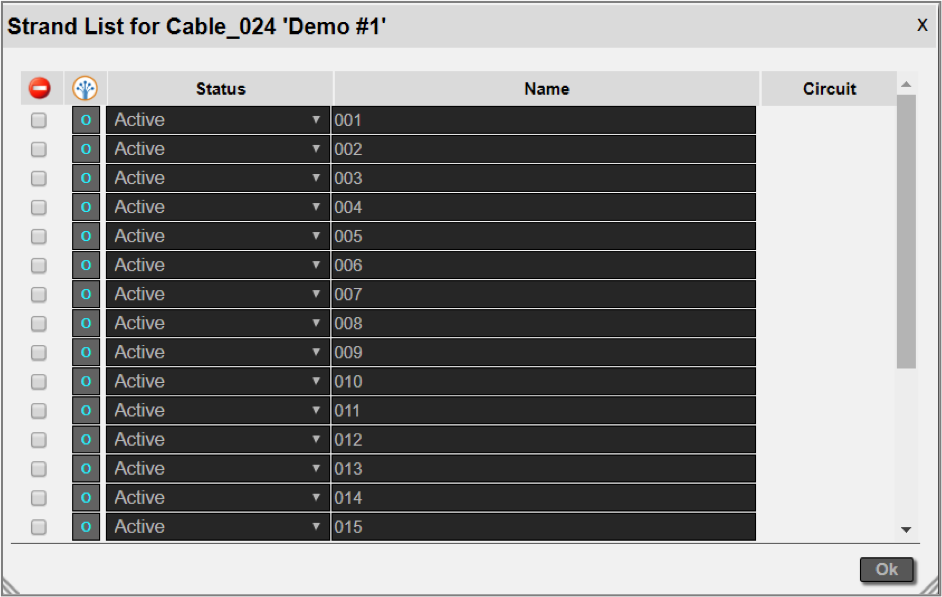 Strand list dialog
Immediately after the cable is created in netTerrain, all the strands that are contained inside of it are disconnected (or dangling): what this means is that each individual strand will not be connected to any port. To connect a strand to an endpoint or switch the current endpoints, simply click on the ‘o’ button, which opens another dialog to manage these endpoints.
 Strand endpoint management
Just click on a strand, select the end ports on both sides, and move on to the next strand.
If you need to disconnect a strand, select it and click on the disconnect button. Any ports that are already in use by strands are marked in red.
Once the strands are connected to endpoints, the endpoint indicator in the strand list is shown in blue. It is important to have your strands terminated, otherwise they cannot be used for circuits (more on that later).
Bottom line? With the above additions, netTerrain OSP users can now sort and manage all types of links — from basic connections to fiber strands.