
In part 1 of this blog series, we went over the basics of Modbus and what support for this well-known industrial protocol exists in netTerrain, along with its limitations.
Here, in the second part of the series, we will go over the Modbus configuration process in netTerrain DCIM.
Our Modbus TCP monitoring implementation is different from other connectors in the sense that it runs as a standalone Windows Console application which acts as a Modbus TCP Client.
This client uses XML configuration files and data already entered in netTerrain (more on that later). This data usually includes IPv4 addresses for each node and possibly a so-called unit number to collect the desired Modbus data from those designated devices and push that device data back into netTerrain using the netTerrain REST API.
As I mentioned in part 1, Modbus TCP devices are not inherently discoverable: there are no standardized ports, registers, or other means from which to identify the device. Information about what properties can be obtained for each Modbus-capable device is typically supplied by the device vendor in the form of a Modbus “register map”, and the choice of information and what Modbus registers/addresses are used for that information is solely at the discretion of the vendor.
Devices that have been tested in our lab include the APC Smart-UPS SMT models, which are Modbus TCP capable and directly accessible by IPv4 address, DataNab Temperature and Humidity Sensors, accessed through a Modbus TCP to Modbus RTU gateway (at the IPv4 address of the gateway) using the unit identifier of the RTU device behind the gateway and ServersCheck SensorGateway, a gateway that independently collects data for all devices behind the gateway and stores the device data in its own Modbus registers, with the unit number of any device defining an offset into the gateway’s Modbus registers.
Prerequisites in netTerrain
Before attempting any Modbus TCP discovery, you must create a Node Type in netTerrain for each desired Modbus device type with a field to identify the IPv4 address. If devices of any Modbus device type are behind a gateway, then you should also add a field to identify the unit number.
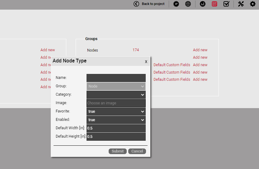 Creating a node type is easy in netTerrain
Based on the vendor’s Modbus register map for each Modbus device type, you then proceed to add a field for each Modbus data value to be collected.
In netTerrain, you should also add a Node for each Modbus device using the appropriate Node Type created earlier, supplying the IP Address (and unit number if applicable) in the designated field. The Nodes can be placed anywhere on any diagram.
As you can see with this process, Modbus is not intended for discovery, since you create the nodes in netTerrain first. The purpose of the Modbus implementation is to monitor environmental variables for devices already registered in netTerrain.
The final prerequisite is to enable REST API access in your netTerrain server. Please check your netTerrain admin guide on how to do that.
Modbus Configuration File
The format of this file is standard XML which include 4 root elements:
<device-info>
<server-id>
<server-port>
<data>
The child elements of <device-info> are:
| <vendor> | Vendor name |
| <product> | Product name or model |
| <description> | Product description |
| <register-map> | Link to Modbus register map |
| <per-unit-offset> | Per-unit offset into Modbus registers for certain gateways |
| <char-swap> | Boolean value (True or 1) to indicate the device requires character swapping to produce correct string values |
| <word-swap> | Boolean value (True or 1) to indicate the device requires word swapping in long (32-bit) integer values |
| <float-swap> | Boolean value (True or 1) to indicate the device requires word swapping in floating point values |
All child elements of <device-info> are optional. The first 4 listed elements are for information purposes only. The <per-unit-offset> is applicable only to those gateway devices that hold all data for devices behind the gateway in their own Modbus registers. The Modbus register maps for such gateways should indicate the value of the offset.
The need to specify <char-swap>, <word-swap>, and/or <float-swap> might be indicated by language in the vendor’s specification for the Modbus device, but it is possible that these will have to be set based on observation of incorrect results being returned, such as a string value with each pair of characters reversed.
The child elements of <server-id> indicate the following:
| <nt-ip-field> | Name of Node Type field in netTerrain holding IPv4 address |
| <nt-unit-field> | Name of Node Type field in netTerrain holding unit number |
The <nt-unit-field> is optional except for devices behind a gateway.
The <server-port> element is optional but can be used if required to override the Modbus TCP port for this device type. The default Modbus TCP port is 502.
The <data> element can contain any number of <property> elements.
Each <property> element will consist of these possible child elements:
| <name> | Modbus property name (for output to console or log file only) |
| <units> | String representing the Units to append to the value (such as °F) |
| <type> | Modbus data type (see list below) |
| <value0> | User-defined string to display for binary value = 0 (type = bit only) |
| <value1> | User-defined string to display for binary value = 1 (type = bit only) |
| <bit-number> | Bit number (0-15 or 0-31) to extract from integer value (type = bit or bool) |
| <divide-by> | Integer value to divide by to produce decimal result (type = int or uint) |
| <function-code> | Modbus function code (must be used with <register>) |
| <register> | Modbus register |
| <address> | Modbus address (used in lieu of <function-code> and <register>) |
| <length> | Number of registers to read (see notes below) |
| <nt-field> | Name of netTerrain Node field to receive the data |
| <poll> | If polling is enabled, is this property polled? |
Example:
<data>
  <property>
    <name>Temperature</name>
    <units>°F</units>
    <type>int</type>
    <divide-by>10</divide-by>
    <function-code>3</function-code>
    <register>100</register>
    <length>1</length>
    <nt-field>Temperature</nt-field>
    <poll>True</poll>
  </property>
  ...
</data>
Now that we understand how to set up netTerrain for Modbus TCP monitoring and how to configure the Modbus config files, we can go over some applications included with netTerrain as supplied Modbus tests — in the next (and final) blog in this series. Stay tuned, and until then: happy documenting!