How to Design an Edge Data Center for Reliability Without On-Site Staff

- Chapter 1: DCIM Software
- Chapter 2: Data Center Power Distribution
- Chapter 3: Green Data Center
- Chapter 4: Data Center Cooling Methods
- Chapter 5: Data Center Environmental Monitoring
- Chapter 6: Data Center Cable Management
- Chapter 7: Data Center Layout
- Chapter 8: Data Center Rack Layout
- Chapter 9: Data Center Rack Density
- Chapter 10: Edge Data Center
- Chapter 11: Data Center Visualization
An edge data center is a small data center located between a central data center and a location in close proximity to the users or devices it serves in order to minimize latency. This definition is appropriate, but it does not capture other important characteristics of such a site:
- It is operated assuming that nobody is on site.
- It is replicated across many locations.
- It is situated in a building or compound that the operator does not control.
The term “edge data center” is used unchanged across setups ranging from large-scale regional data centers down to unmanned telecom towers, small individual client racks, and tiny micro data centers. As an unmanned location is the toughest case, and since anything designed for it can work in manned locations as well, we chose it as the design case.
Cybersecurity, network architecture, and workload selection fall outside the physical scope of this guide. This article discusses five best practices and provides an example for each.
Summary of key edge data center best practices
| Best practice | Description |
|---|---|
| Design for an unmanned site from day one | Design for unmanned operation from the outset; adapting a manned design later duplicates effort and cost. |
| Standardize outdoor and indoor sites into one or two classes each | Define one or two standard classes for indoor and outdoor sites, and specify the required protection in clear, organization-specific terms. |
| Establish site-specific autonomy before accepting the standard | Determine battery autonomy from site conditions, including the equipment boundary, battery thermal management, and generator start and ramp-up times. |
| Check capacity adequacy against site conditions | Validate cooling capacity against local temperature, humidity, and minimum-load conditions, and provide N+1 cooling redundancy. |
| Update and track assets, attributes, and their movements | Consider any move, replacement, or re-patching complete only after updating the asset register. |

netTerrain. Battle-tested & affordable DCIM Software
-

Manage data center floor plan, rackspace, cabling, power distribution, and more
-

Use analytics to optimize data center capacity and energy costs
-

Deploy quickly using asset discovery tools and pre-built integrations
Design for an unmanned site from day one
Treat the absence of an engineer as a key design requirement from day one.
Edge data centers are built in one of the following three physical forms:
- A standalone stick-built building
- A complete containerized module
- Outdoor cabinets
But one condition is common to all of them, which shapes the rest of this section: The operations crew doesn’t sit inside them.
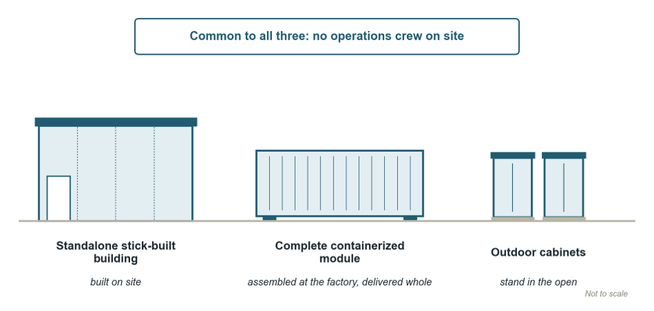
Every intervention at an unmanned site requires travel, and the burden increases across multiple locations. A published practice involves annual preventive maintenance and thermographic inspections every six months. Combining both activities can reduce the requirement to two site visits per year. For example, across forty sites:
40 sites x 2 visits per site = 80 visits per year
At such a site, maintenance is divided into two types of activities, and an unmanned site treats them differently:
- Preventive maintenance, being planned, remains the same because the visit is pre-scheduled and only its cost changes.
- Corrective maintenance begins only after a failure that may occur at an unpredictable time, and it requires someone to attend to the equipment. That person is hours away. So, the design requirement is the capability to carry the site through the interval between the failure and the arrival.
The initial response to any failure must be automatic, as the corrective attendance is expected in hours. The table below lists the failures expected at an unmanned site and, for each one, the designed response, who attends and when, and how long the automatic response holds.
| Failure mode | Designed response | Who attends, and when | How long the automatic response holds |
|---|---|---|---|
| Cooling fails above the limit | Rack doors open automatically | The provider, within the agreed response time | Doors buy time until the room air warms |
| Fire alarm | Doors open for the extinguishing gas | Fire service at once; arrival depends on location | Not applicable; the gas acts |
| Battery overheating | Automatic shutdown | The provider, within the agreed response time | The site is down until someone arrives |
| Utility supply fails | Transfer switch selects the standby source; UPS covers the gap | Nobody if the standby takes over; the provider if not | UPS for its rated backup time, then the standby source |
| One cooling unit fails, with a standby unit fitted | The standby unit takes the load | The provider, within the agreed response time | Until a second unit fails |
For instance, one manufacturer says its indoor products can also suit edge locations. Its datasheet specifies automatic rack-door opening when cooling fails and temperature exceeds the threshold or a fire alarm activates. These features provide proper protection. However, the datasheet does not address who responds afterward. Staff can act at manned sites, but unmanned sites have no personnel available.
Between preventive maintenance site visits, remote monitoring answers when somebody needs to visit. Consider a cooling unit with a constant airflow fan—with a clogged air filter, the fan controller raises fan speed to maintain normal airflow, for which the fan draws more power. The site looks normal, but rising power indicates the need for filter maintenance. Evidence-based visits like this are classed as condition-based maintenance. If a breakdown occurs, the system raises an alarm, and a corrective maintenance site visit takes place. Therefore, monitoring does not replace scheduled visits; it determines when an extra visit is worth making and where.
When the design is finalized, assign responsibility for every site activity. Document service-level agreement (SLA) response and site-arrival times separately for working hours, after-hours, and holidays, as faults can occur at any time. Track spares used and restocked in the monitoring system so the person taking the call can confirm the spare is at site before sending a technician.
Add adequate redundancy and a standby source. Hold the frequently used mandatory spares at the site or a designated nearby location. Then design the survival time considering it to outlast the journey and restoration using a rule other than the autonomy formula (Section 3):
survival time > (maximum time to arrive under the SLA + the expected restoration time) x factor of safety
Segregate response from restoration. Automate fault responses but use remote resets carefully: They can restore service without anyone inspecting the equipment. Since a trip may result from an overload or a genuine fault, configure monitoring to identify the cause. Permit one remote reset only after monitoring confirms that the trip was not a fault and the cause has cleared; otherwise, wait for an on-site inspection.
Decide what is to be monitored, considering what it costs when the equipment fails. The monitoring application must monitor all parameters that can disrupt IT load, put equipment at risk, or compromise site security. An unmeasured parameter at an unmanned site is unseen until someone reaches there.
netTerrain recognized as “Major Player” in IDC MarketScape’s 2026 Datacenter Facilities Management Software Vendor Assessment
Standardize outdoor and indoor sites into one or two classes each
Without standardization, edge sites gradually develop unique designs, often for valid local reasons. A different cabinet or cooling unit may seem insignificant, but across 40 unattended sites, each variation increases spare-stock requirements, training needs, documentation, commissioning work, and equipment-transfer effort. Standardization therefore helps control costs.
Variety enters mostly through two doors: location and IT load. Sites differ depending on where the equipment will stand, which may be indoors or outdoors. Sites also differ in their IT load requirements.
The envelope is the physical boundary that separates the equipment from its surroundings, protects it from rain, dust, and water, and retains the cooled air needed to maintain operating conditions. Envelope requirements depend first on whether the equipment is installed indoors or outdoors:
- Indoors, either a sealed cabinet or the building provides the protection. A sealed cabinet provides its own enclosure, while open racks rely on the building for protection. When the building serves as the envelope, clearly document the required standards and specifications, as the datasheet may not cover them.
- For outdoor installations, there is no building envelope to rely on, so the equipment must provide its own protection.
Capacity is the second door. Makers of self-contained edge products publish their ranges in steps. When we read the datasheets of three of these makers, we find that their products fall into four classes. Interestingly, the two largest come from one maker. The table below compares the classes by number of IT racks, total IT load, load per rack, external dimensions, and the protection level the maker specifies. For engineering purposes, read the table with a simple rule: the IT power a rack consumes approximately equals the cooling load it requires.
| Class | IT racks | Total IT load | kW per rack | External dimensions | Protection and ambient temperature, as each maker states it |
|---|---|---|---|---|---|
| 1. Single enclosure | 1 | 1.3, 2.6, or 5.8 kW | 1.3 to 5.8 | 2000 x 800 x 800 to 1200 mm, 42 U, plus roof or wall-mounted cooling | IP54, unconditioned spaces; temperature not stated |
| 2. Converged single-row cabinet | 0 to 10 | 25 kW | about 7 | 2000 x 600 to 7400 x 1350 mm | IP20, indoor only; -40 to +55 °C (-40 to +131 °F), depending on the outdoor unit chosen |
| 3. Prefabricated module | 2 to 14 | 40, 60, or 80 kW | about 10 | 3245 x 3440 x 4692 to 12192 mm | Weatherproof, no IP code stated; -20 to +45 °C (-4 to +113 °F) exterior |
| 4. Large prefabricated, two rows | up to 26 | up to 200 kW | up to 17 | 3330 x 5810 x up to 15850 mm | Weatherproof, no IP code stated; -30 to +50 °C (-22 to +122 °F) exterior |
U = rack unit, 1.75 in (44.45 mm) of rack height.
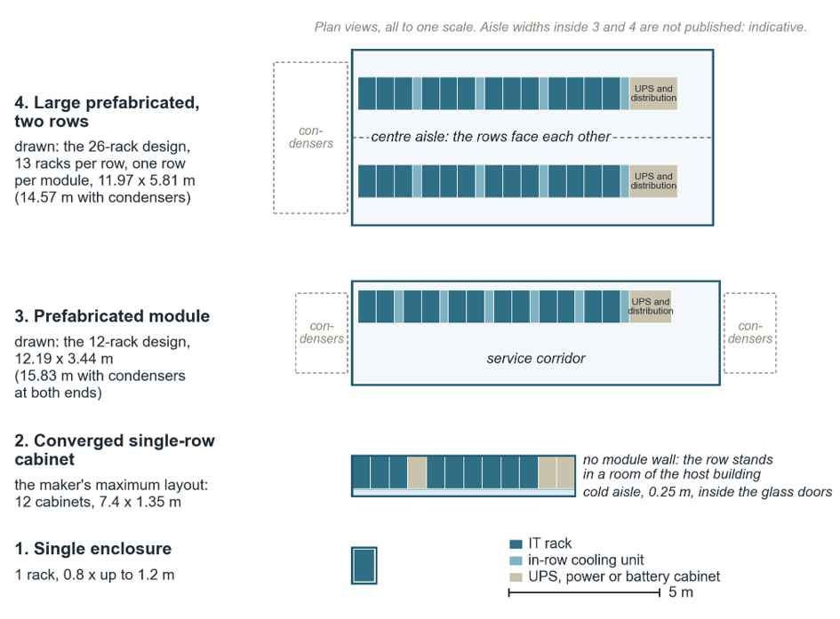
These capacity breakpoints form the basis for estate standardization: Select a standard from these classes rather than specifying a rack capacity freely. However, the protection class does not necessarily increase with rack size. For example, the smallest cabinet may offer IP54 protection for unconditioned spaces, while a much larger cabinet may offer only IP20 and still suit indoor use.
Where a maker publishes no IP code or no temperature range, the table says “not stated.” Therefore, specify the required environmental rating separately rather than assuming it from the equipment’s size or capacity. For indoor sites, adopt one or two classes. Similarly, implement one or two classes for outdoor sites. Write down the required protection for each class in your own terms. Do not borrow the term that the datasheet uses.
Establish site-specific autonomy before accepting the standard
Self-contained edge products come with a specified battery backup time. The maker has chosen that figure for an assumed site, but your site will not be identical. In practice, edge data centers need backup ranging from a few minutes to several hours. The standard departs from the actual requirement in three respects: what the product includes, how its battery performs across temperature variations, and what the site shares with a telecom tower.
The assumption that the datasheet runtime covers everything is the first trap for any site. An equipment list alone cannot show the boundary of an edge data center. For example, while some containers include direct-current power supplies, UPS batteries, and a generator inside, others house some of these outside. So, as a first task, the designer must determine where the boundary actually falls. Although the boundary is real, each product draws it in a different place.
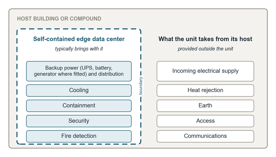
Site layouts differ. Some place the generator inside the main enclosure, while others install it in a separate housing. One principle remains constant: Batteries require a temperature-controlled compartment, even within a shared enclosure. Valve-regulated lead-acid (VRLA) batteries perform optimally near 25 °C (77 °F). For each additional 8 to 10 °C (14 to 18 °F), their service life can fall by about half. This is why some outdoor telecom cabinets actively cool the battery compartment.
Excessively low temperatures create another problem. They slow the battery’s chemical reactions and reduce its available capacity, prompting sites in colder regions to heat the battery area. Lithium iron phosphate batteries introduce a different constraint. Manufacturers commonly permit discharge below 0 °C (32 °F) but restrict charging below it. Following an outage during a freezing night, the battery may remain unable to recharge until it warms up. At an unmanned site, no one may notice that the backup reserve has not been restored.
Another trap relates to telecom tower sites within the access network, where radio base stations operate. Core facilities require a separate assessment. Operators often locate edge-computing equipment at towers because these locations already have power and connectivity.
The edge load can receive power through two main arrangements, as shown below.
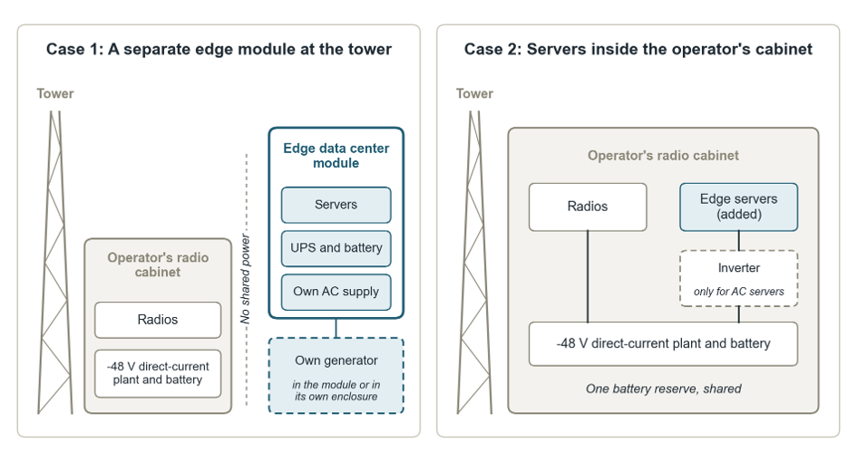
A standalone edge module has an independent AC system, generator, and UPS. Its power system remains separate from the tower batteries, so it cannot draw on the tower’s battery reserve.
Servers installed within the operator’s cabinet follow a different arrangement. They draw power from the existing -48 V direct-current plant, either directly or via an inverter. That plant was originally designed for radio equipment rather than additional computing loads. As a result, the servers consume part of the same battery reserve as the radios, reducing the backup available to both. The table below presents typical battery backup durations.
| Site configuration | Typical battery backup duration in practice |
|---|---|
| Prefabricated module, data center tradition | 5 minutes in the standard design |
| Converged indoor cabinet | 15 to 30 minutes |
| Telecom plant, radio tradition | 3 to 8 hours in the USA, 2 hours or less in Europe |
| Off-grid sites | No battery at all; diesel generator and solar |
You can’t get three facts from a datasheet, so establish them in this order:
- Determine which side of the boundary the generator, the direct-current plant, and the batteries fall on.
- Identify the temperature-control methods used to heat and cool the batteries.
- Record whether a generator is available, along with its start time and ramp-up time to take up the required load.
These facts belong to the machine, wherever it stands. Determine them at the site during design before accepting the figures stated for the product.
Determine autonomy from the specific site conditions, using the calculation to establish the minimum required level:
minimum autonomy = [(start attempts x time per attempt) + ramp time + clean shutdown time] x design margin
Base every parameter on the actual site conditions. The controller settings define the number of start attempts and allowed time for each attempt, the generating set documentation provides the ramp-up time, and the application requirements determine the clean-shutdown sequence. Start with the requirements on the ground, then compare them against the standard configuration supplied with the product.
Across 40 sites, a designer may find several different power configurations, so standardizing autonomy is not practical. Even if two sites use the same enclosure, their boundaries might not match.
Check capacity adequacy against site conditions
A self-contained edge data center arrives with its cooling. The manufacturer sizes it. The designer only checks its rated capacity, but the real site rarely matches the condition in which the manufacturer tested it.
Rated capacity can mislead in three ways: the rating conditions, the actual site load, and equipment downtime.
The first trap is the rating condition. Consider a manufacturer that specifies a 12.5 kW rack-mounted direct-expansion system based on 37.8 °C (100 °F) entering air, 20% relative humidity, and 35 °C (95 °F) outdoor air. The indoor section transfers server heat through insulated copper refrigerant lines to the outdoor condenser. Therefore, 12.5 kW represents capacity under the stated test conditions, not a universal maximum.
Humidity also affects usable cooling capacity. At 20% relative humidity, the system removes little moisture, leaving most of its capacity available for sensible cooling. In a humid environment, some capacity shifts to latent cooling as the system removes moisture from the air.
The second trap is the actual site load. Low IT demand reduces the sensible cooling requirement, but moisture can continue entering through infiltration or door openings. At an unmanned edge site, prolonged operation at low load can therefore leave the cooling system with limited dehumidification capacity while humidity rises toward the dew point.
The control sequence should address both temperature and moisture, with dew-point or humidity monitoring, appropriate dehumidification control, and alarms for abnormal conditions. Manufacturer-specific minimum-load limits should also be checked rather than treated as universal requirements. The maker’s installation manual warns that very low cooling demand, poor enclosure sealing, or prolonged door opening can drive humidity beyond acceptable limits and require dedicated dehumidification.
The third trap is equipment downtime. With nobody at the site, a unit can stop without anyone noticing. At least one manufacturer offers its cooling in an N configuration: just enough units for the load, with no standby unit. The same product opens its rack doors automatically when cooling fails and the temperature exceeds the limit. Both matter because a sealed cabinet holds almost no reserve of cool air:
Time to the limit = (air density x free air volume x specific heat x permitted temperature rise) / IT load
The figures below are illustrative assumptions: one 42 U enclosure, about 1 cubic meter of free air, a 10 K (18 °F) rise, and a 5.8 kW IT load.
Time to the limit = (1.2 x 1 x 1.005 x 10) / 5.8 = 2.1 seconds
A sealed cabinet’s thermal air reserve is measured in seconds. Opening the door lets the cabinet draw on the building’s air volume.
Check the rating against the site conditions in this order:
- Review the rating conditions, not just the capacity.
- Compare them with the site’s summer design dry-bulb temperature and the required indoor condition.
- Ask the manufacturer for the capacity, its sensible and latent split, fresh-air allowance, and the moisture-ingress assumption at those conditions.
- Specify N+1 cooling: one unit more than the load needs, so any one unit can fail or be serviced without losing capacity.
Update and track assets, attributes, and their movements
The asset register matches the site exactly on handover day. After that, any unit movement, swapping, or repatching without an update makes the register less accurate. However, nobody will notice the gap until a failure occurs.
Before touching the rack, ascertain six things: the installed equipment, its feeding circuits, cable routes, spare capacity, metering logs, and what changed last. The records must supply them without anyone physically searching the site. If they cannot, troubleshooting begins with reconstructing missing information rather than restoring service.
The gap hides well inside a table. A spreadsheet can store individual details, and a dedicated maintainer at a small facility may keep drawings and tables up to date. But a table row cannot show which loads are affected by opening a particular breaker. Data center infrastructure management software maps those relationships and can trace the complete path. It also keeps two functions separate: an alarm indicates that a failure has occurred, while the asset record identifies the exact equipment affected, its location, and the circuit involved.
Network tools can identify a device but cannot tell you where it sits in the rack, its U position, or which breaker supplies it. A person must add those details to the record. So, treat the record entry as part of the job. Consider any move, swap, or repatch complete only after recording the change in the register, including the unit’s location and the circuit that feeds it.
Recommendations
Specify what happens when the enclosure unlocks itself
When specifying access control, do not select the lock alone. Specify the cabinet’s expected behavior under failure conditions, including which doors to open in response to a cooling failure or a fire alarm. When a door opens automatically, document clearly whom to notify and what that person does.
Survey the host building before fixing the enclosure choice
A single site visit identifies two distinct types of failure, but after the order is placed, this opportunity is lost. The first question is whether the equipment can physically enter the site, so confirm the weight and dimensions. Note that one some systems have a weight up to 17 metric tonns per module with empty racks and battery cabinets, and a maximum transport length of 52 ft (15.85 m). Therefore, evaluate the floor loading, the access route, the dimensions of doors and elevators, and the environmental rating.
The second question is whether the equipment can operate once it is in position. Verify the condenser location and the structure that will support it, the refrigerant pipe run and allowable lift, the condensate drain arrangement, and the permissible noise level at the site boundary.
Prove every automatic response and record the rack position at handover
Test every system intended to take over on a failure and prove it does so at the unattended site. Before you sign off, record the rack position, U position, and breaker association at handover, and have an authorized person check and accept the recorded details.
Infrastructure clarity for organizations across all industries
Conclusion
An edge data center is usually defined by its proximity to the users or devices it serves. This article has looked at it through the conditions under which it must operate: an unmanned site, a replicable design, and a host building that the operator does not control. Under those conditions, a small oversight can be repeated across every site and remain hidden until something fails far from anyone who can fix it. The common thread among all of these considerations is simple: the site must behave as designed long after the installers have left. An edge site built on that principle may rarely need a visit, and that may be the clearest measure of its success
