Data Center Layout: Tutorial & Best Practices

Data center layout is the physical arrangement of infrastructure assets so they can be operated, maintained, and expanded without compromising reliability. In practice, layout decisions are a balance of thermal management, electrical distribution, connectivity infrastructure, service access, operational visibility, and future scalability. Equipment requirements drive asset location, but they also directly impact what the physical space can support. These decisions shape not only capacity and density but also the long-term coherence of the operating environment.
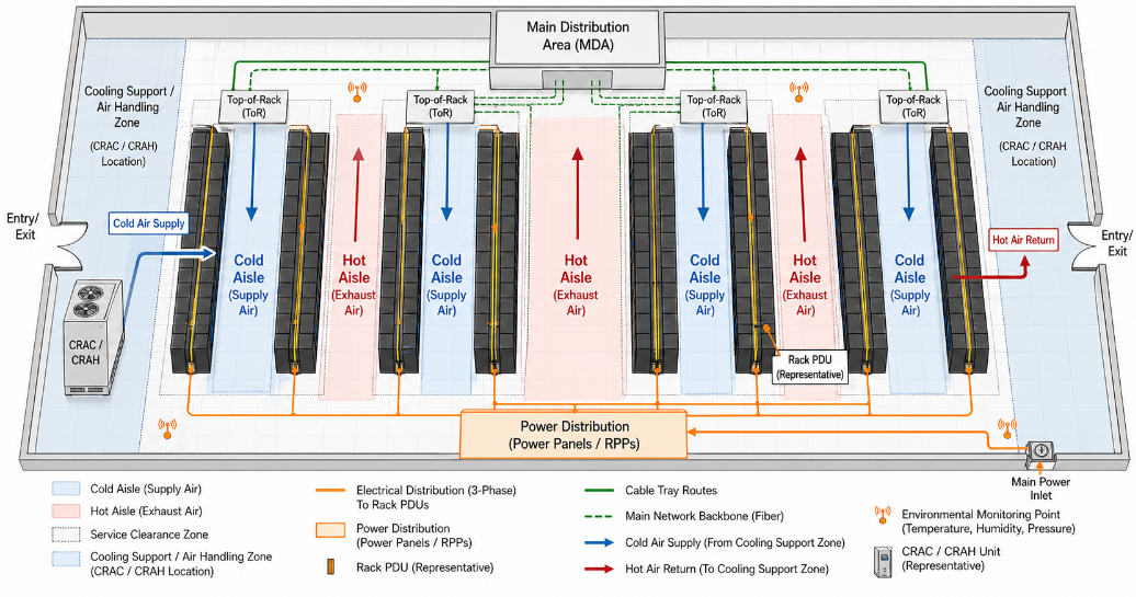
The implementation of data center layout best practices varies across use cases, but the principles themselves do not. Across enterprise facilities, colocation deployments, edge sites, and high-density compute zones, the same underlying concerns continue to define good physical design. This article examines those common principles through a set of best practices organized around the core physical logic of layout. The table that follows summarizes those practices, and the sections after it explain how they are applied across different operating contexts.
Summary of data center layout best practices
The table below summarizes the best practices through which this article approaches data center layout, representing the principles that remain consistent across rack-based data center environments. Each entry reflects a recurring aspect of physical design.
| Best Practice | Description |
|---|---|
| Enforce thermal layout discipline | Organize airflow paths, density zones, and cooling resources so thermal conditions remain predictable at the rack, row, and room levels. |
| Standardize racks and rows | Maintain consistent rack alignment, spacing, and physical organization to support cooling, serviceability, and capacity planning. |
| Install redundant electrical distribution | Arrange A/B feeds, ATS/STS devices, PDUs, and rack power paths so redundancy is preserved through the physical layout. |
| Plan connectivity and demarcation | Design cable pathways, carrier entry, patch fields, and related network infrastructure to keep connectivity orderly, traceable, and scalable. |
| Manage operational access and service clearances | Preserve adequate working space around racks, cooling systems, and electrical equipment to support safe maintenance and uninterrupted operations. |
| Ensure environmental monitoring and operational visibility | Place sensors, labeling, and physical documentation so that conditions, dependencies, and infrastructure status remain visible over time. |
| Design for future scalability and modularity | Reserve space, pathways, and infrastructure headroom to enable the environment to expand without forcing major redesign. |

netTerrain. Battle-tested & affordable DCIM Software
-

Manage data center floor plan, rackspace, cabling, power distribution, and more
-

Use analytics to optimize data center capacity and energy costs
-

Deploy quickly using asset discovery tools and pre-built integrations
Fundamental principles over use case
The best practices in the table above are not presented as isolated design tactics nor as a checklist tied to any one facility type. Instead, they are grouped around the recurring physical concerns that define data center layout across modern rack-based environments. Thermal management, electrical distribution, connectivity infrastructure, service access, operational visibility, and future scalability each impose real spatial and operational constraints on the room. The purpose of this section is to show why those concerns produce a stable set of best practices even when different use cases lead to considerable variation in implementation.
Layout is the point where technical requirements become physical decisions. Every data center must translate cooling, power, connectivity, and service requirements into a workable arrangement of racks, rows, pathways, equipment zones, and access areas. This is why a best-practices framework based on recurring physical constraints is more durable than one organized only around facility type. Enterprise facilities, colocation environments, edge deployments, and high-density compute zones may differ significantly in scale and operating model, but they are all still governed by the same basic physical requirements.
Thermal and electrical requirements are fundamental because they define the operating limits of the room. Airflow paths, row orientation, density zoning, and cooling-resource placement determine whether heat can be removed predictably at the rack, row, and room levels. Electrical distribution imposes a parallel set of layout constraints: redundant paths, automatic transfer switch (ATS) and static transfer switch (STS) devices, power distribution units (PDUs), busways, tap-off units, and rack feeds must be arranged so that resilience is preserved in the physical design, not only in the electrical diagram. For both thermal and electrical, layout determines whether the infrastructure can perform as intended under real operating conditions.
Connectivity infrastructure introduces its own spatial logic, especially where demarcation, traceability, and scale matter. Cable pathways, carrier entry points, patch fields, meet-me rooms, and network equipment areas must be planned so that connectivity remains orderly and supportable over time. This is especially visible in colocation environments, where cross-connect clarity and tenant separation are central to the operating model. However, the same principle applies in enterprise and edge environments as well: Network infrastructure must be physically organized so that it can be traced, maintained, and expanded without creating operational confusion.
Operational access and visibility determine whether a layout remains usable after initial deployment. Service clearances, maintenance paths, sensor locations, labeling, rack elevations, and physical documentation all shape how effectively operators can maintain and troubleshoot the environment. These elements are sometimes treated as secondary to equipment placement, but they are part of the layout itself. A room that cannot be safely serviced, clearly understood, or accurately monitored will become harder to operate even if the original rack, cooling, and power design appeared sound.
Future scalability is what prevents a sound layout from degrading as the environment or the operational needs change. Space for additional rows, pathway headroom, spare power and cooling capacity, and modular room organization all help the layout absorb growth without losing coherence. Without this provision, even well-designed rooms tend to accumulate exceptions: temporary cable routes become permanent, isolated high-density loads exceed the original cooling assumption, and new equipment begins to break the logic of the original rack and row plan. Good layout design therefore accounts not only for the initial deployment but also for the changes the room is likely to experience over time.
The use case changes implementation, but it does not replace fundamental design principles. An enterprise facility may emphasize internal standards, centralized control, and predictable service workflows. A colocation facility may place greater emphasis on tenant separation, demarcation, metered delivery, and cross-connect discipline. An edge deployment may compress the same requirements into a smaller footprint, where remote visibility and repeatable modules become more important. A high-density compute zone may intensify thermal and electrical constraints to the point that containment, localized cooling, and more deliberate power planning become unavoidable. These differences change how the principles are expressed, but they do not create separate rules for good layout.
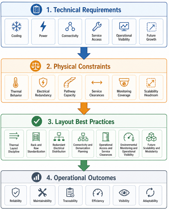
Taken together, these points organize data center layout around a stable set of best practices rather than around facility types alone. The sections that follow examine each practice in turn: first, establishing its role in the physical design of the room, then showing how implementation shifts across different data center contexts without altering the principle itself.
Enforce thermal layout discipline
Thermal layout discipline begins with the assumption that heat is not distributed evenly across a room. Rack density, equipment orientation, airflow paths, and cooling-resource placement all help manage thermal conditions to predictable values instead of drifting into localized hotspots. A strong layout separates supply and return air, aligns rows around a coherent cooling strategy, and organizes high-density loads so that cooling resources are matched to actual thermal demand while mitigating the risk of runaway.
The specific cooling approach may vary by context. Traditional room-based strategies may rely on CRAC or CRAH units, while other environments may use in-row cooling, containment, rear-door heat exchangers, or liquid-assisted systems. The layout implications are different in each case, but the underlying requirement is the same: Heat must move through the room in a controlled and predictable way.
To this end, several layout decisions are especially important:
- Airflow separation: Hot and cold air streams should be managed so that return air does not mix unnecessarily with supply air.
- Density zoning: Higher-density racks should be grouped or planned so cooling capacity can be applied deliberately.
- Cooling-resource placement: Cooling equipment should be positioned according to load profile, airflow behavior, and service access, not simply open floor space.
The implementation environment is important as well:
- Enterprise environments often benefit from uniform row strategies and internal standards.
- Colocation environments may need to accommodate tenant-driven exceptions while still preserving room-level thermal discipline.
- Edge deployments compress the same thermal concerns into smaller rooms or enclosures, where airflow paths can be easily disrupted.
- High-density compute zones intensify the problem and may require containment, localized cooling, or liquid-assisted approaches.

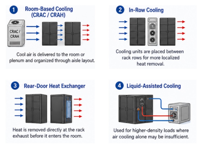
The practical takeaway is that thermal zones should follow load profiles, not just floor geometry. A layout that looks orderly on a floor plan can still perform poorly if heat generation, airflow movement, and cooling capacity are not aligned.
Standardize racks and rows
Rack and row standardization preserves the operating logic of the room. Consistent rack orientation, row spacing, rack naming, and physical alignment make the environment easier to cool, cable, document, and maintain. Without this discipline, each new asset can become an exception that weakens the layout around it.
A strong layout should dictate how racks are placed, powered, cooled, labeled, and serviced. The reverse approach—modifying the room in an ad hoc manner for each new asset—tends to create long-term operational problems such as disrupted airflow patterns, complicated cable pathways, uneven service access, and less reliable capacity planning.
Standardization also aids in overall system documentation, which is essential for effective usage of any given data center layout. Rack elevations, row labels, asset records, and cable maps become more useful when the physical environment follows a predictable structure. This is especially important as the room grows because operators need to understand not only where equipment is located but also how that equipment relates to power, cooling, connectivity, and service workflows.
As with the thermal layout, the actual implementation of these principles differs based on the environment:
- Enterprise facilities can often enforce internal standards across the room.
- Colocation providers must balance standard facility design with varied tenant footprints.
- Edge deployments benefit from repeatable rack or enclosure modules that can be replicated across sites.
- High-density zones may require tighter alignment between rack layout, cooling adjacency, and power distribution.
Install redundant electrical distribution
Electrical distribution is one of the clearest examples of layout directly affecting reliability. A redundant power design must be reflected in the physical arrangement of feeds, distribution equipment, rack power paths, and maintenance access. If the power chain is difficult to trace or service, overall confidence in both system reliability and redundancy will be affected.
Layout decisions such as A/B distribution paths, ATS or STS devices, busways, tap-off units, rack and room PDUs, and cable routing all shape how resilient the room actually is. The goal is not only to deliver power but to preserve separation between circuits, maintain clear fault domains, and reduce confusion during maintenance or failure response.
Several physical layers should be considered together:
- Source and distribution equipment: Utility feeds, generators, UPS systems, switchgear, panelboards, and PDUs must be arranged with access, separation, and maintainability in mind.
- Room-level distribution: Busways, tap-off units, overhead or underfloor pathways, and branch circuits should support predictable routing and clear capacity planning.
- Rack-level delivery: A/B feeds, rack PDUs, cord routing, and load balancing should be organized so redundant paths remain distinct and traceable.
Implementation of these layout decisions varies across facility types but ultimately rely on the same principles and constraints:
- Enterprise environments often emphasize control, maintainability, and internal standards.
- Colocation environments require segmented, metered, and tenant-aware power delivery.
- Edge deployments may use simplified distribution schemes, but still need resilience and service clarity.
- High-density environments require more deliberate feed planning because rack power demands can quickly exceed assumptions built for lower-density rooms.
Plan connectivity and demarcation
Connectivity and demarcation planning treats network infrastructure as both a physical layout concern and a digital logic problem. This sort of hybrid thinking encompasses cable pathways, carrier entry points, meet-me rooms, patch fields, fiber trays, cross-connect areas, and network equipment locations in the determination of overall network reliability.
To this end, the layout should make it clear where external services enter the facility, where responsibility changes hands, where connections are patched, and how pathways support future growth. Without this planning, cable infrastructure tends to expand through convenience rather than design. Over time, this creates traceability problems, obstructed pathways, crowded patch fields, and operational uncertainty.
Associated layout concerns include:
- Carrier entry and demarcation: External services should enter through planned locations with clear ownership and handoff points.
- Pathway organization: Overhead trays, underfloor routes, conduits, and ladder racks should preserve separation, capacity, and accessibility.
- Patch and cross-connect fields: Connection points should be labeled, documented, and arranged so changes can be traced without excessive manual investigation.
Colocation environments make this especially visible because demarcation and cross-connect clarity are central to the operating model. However, the principle applies just as strongly in enterprise environments, where internal handoffs and system dependencies must remain clear. Edge environments may have smaller pathway systems but still require disciplined labeling and documentation because remote troubleshooting depends on accurate physical records. High-density compute zones may require expanded fiber capacity and more deliberate network aggregation as equipment density increases.
The practical takeaway is to treat demarcation as planned infrastructure, not overflow space. Connectivity should be laid out so that it can be traced, maintained, and expanded without undermining the physical order of the room or the digital logic of the network.
Manage operational access and service clearances
Operational access and service clearances determine whether the layout remains maintainable after equipment is installed. Clearances around racks, electrical gear, cooling systems, cable pathways, and service corridors are not unused space; they are required for safe work, equipment replacement, troubleshooting, airflow management, and emergency response.
A layout that maximizes equipment density at the expense of access can create long-term operational risk. Racks may be difficult to service, panels may be obstructed, cooling equipment may lack maintenance room, and cable pathways may become hard to reach. These problems often appear after deployment, when the room begins to absorb new equipment, temporary workarounds, and operational changes.
This is support-model agnostic but is exacerbated in certain implementation contexts. In an enterprise facility, internal teams may have more control over service procedures and equipment standards. In a colocation environment, the layout must balance rentable density with provider access, customer access, and clear responsibility boundaries. Edge sites often face tight footprints, making disciplined clearance planning especially important. High-density environments can introduce additional conflicts because larger power and cooling infrastructure may compete for the same service space.
Good layout protects access as deliberately as it protects capacity. This includes front and rear rack access, electrical working clearances, cooling-system service areas, removable-panel access, temporary staging zones, and safe movement paths for equipment and personnel.
Ensure environmental monitoring and operational visibility
Environmental monitoring and operational visibility extend the layout beyond equipment placement. A data center must not only function physically; it must also be observable. Sensor placement, labeling, rack documentation, cable records, floor plans, and infrastructure maps all affect how well operators can understand the room as conditions change.
Monitoring provides the data needed to identify changing conditions, while visibility provides the context needed to interpret that data. Both depend on physical layout. Sensors must be placed where meaningful variation occurs, and labels or documentation must reflect the actual relationships between assets, pathways, power sources, cooling zones, and service areas.
Important visibility layout elements include:
- Environmental sensing: Temperature, humidity, leak detection, airflow, and other sensors should reflect actual operating risk and variation.
- Infrastructure identification: Labels, rack elevations, panel schedules, and cable records should make physical dependencies understandable.
- Operational context: Floor plans, dependency maps, and asset records should remain accurate as equipment is added, moved, or retired.
Different environments may emphasize different aspects of monitoring and visibility, but the core goal remains the same:
- Enterprise environments may emphasize facility-level and rack-level visibility for internal operations but likely lack the scope for discrete observability when multiple facilities are concerned.
- Colocation environments often require both provider visibility and tenant-facing visibility, especially where responsibility boundaries matter.
- Edge environments place heavy emphasis on remote observability because on-site support may be limited.
- High-density environments require more granular monitoring because small changes in load, airflow, or cooling performance can have larger consequences.
In all cases, the goal is to place sensors and observation entry points where operating conditions actually change so that a layout can be leveraged or scrutinized as needed. Monitoring should not merely document the room; it should reveal the conditions that affect reliability, maintainability, and response time.
Design for future scalability and modularity
Future scalability and modularity determine whether the layout can absorb change without losing coherence. A good layout is not only organized for the initial deployment, but also preserves the ability to add capacity, extend pathways, increase power and cooling support, and maintain a consistent operating model over time.
Scalability is not simply a layout with additional, unused floor area. A room may have open space but still be difficult to expand if power capacity, cooling capacity, cable pathways, demarcation areas, service clearances, and monitoring coverage were not designed for growth. Conversely, a smaller room with little excess floor space can remain adaptable if its expansion paths are clearly planned and its infrastructure systems are modular.
This is where many layout problems emerge gradually. A new rack is placed outside the standard row logic. A temporary cable path becomes permanent. A high-density deployment consumes spare cooling capacity. A patch field fills faster than expected. Each exception may seem manageable on its own, but together they weaken the original design and make future changes harder to control.
Different environments face different scalability pressures. Enterprise facilities may grow by department, platform, or business unit. Colocation facilities grow according to tenant demand and commercial utilization. Edge environments often scale by repeating compact modules across multiple locations. High-density environments may be limited less by floor area than by thermal and electrical headroom. However, the practical takeaway remains the same: Plan for expansion paths, not just empty space. Regardless of use case, scalable layout depends on reserved capacity, modular organization, pathway headroom, and enough discipline to prevent growth from becoming a series of unrelated exceptions.
Infrastructure clarity for organizations across all industries
Conclusion
Data center layout is best understood as the physical expression of recurring technical requirements rather than some fixed room template tied to deployment model. Enterprise facilities, colocation environments, edge sites, and high-density compute zones each place different pressures on the physical space, but the underlying best practices remain consistent. Thermal discipline, rack and row standardization, redundant electrical distribution, connectivity planning, service access, operational visibility, and future scalability all reflect the same basic need: to translate infrastructure requirements into a room that can be operated with clarity and confidence.
A sound layout therefore depends less on facility type alone than on the coherence of the physical design. Cooling paths, power routes, cable infrastructure, service clearances, monitoring points, and expansion paths must work together as part of the same operating environment. When these elements are planned deliberately, the data center is easier to maintain, easier to troubleshoot, and better prepared for change. When they are treated as separate concerns, the layout tends to accumulate exceptions that weaken reliability over time. Good layout is not simply an efficient use of space; it is the physical framework that allows the facility to remain reliable, understandable, and adaptable throughout its operating life.
