Data Center Cable Management: Tutorial & Best Practices

Poor cable management is a critical risk factor for service stability in data centers. A lack of structure and maintenance in the physical layer can cause routine tasks, such as reseating an uplink in a congested rack, to inadvertently disrupt adjacent connections, trigger failovers, and impact service.
Dismissing cable management as an “office chore” overlooks its function in risk management. Issues like poor labeling, congested pathways, and increased risk during maintenance develop slowly over time as temporary connections become permanent, labels degrade, and pathways exceed capacity. This degradation makes the environment harder to understand and riskier to operate, increasing uncertainty about changes and the effort required for troubleshooting.
Cable management is not just aesthetic; it’s infrastructure governance that dictates the reliability of system changes, speed of issue isolation, and alignment of physical and logical design. The impact is measurable, leading to longer incident resolution, increased operational risk, and reduced confidence in changes, ultimately resulting in high risk due to reduced reliability and predictability.
Sustainable data center environments require a structured physical implementation, accurate connectivity representation, and clear ownership/enforcement of standards. Without these, environments degrade through unmanaged change. Good cable management ensures that routine tasks truly remain routine.
Summary of key data center cable management concepts
| Concept | Operational Meaning and Impact |
|---|---|
| Standardization | Consistent labeling, color coding, and routing conventions reduce human error and speed up troubleshooting. |
| Physical Segregation | Clear separation of power and data preserves airflow, improves safety, and prevents interference. |
| Mechanical Integrity | Proper bend radius, strain relief, and structured bundling protect fiber and copper from premature failure. |
| Documentation Accuracy | Connectivity records reflect the real environment, minimizing wrong-circuit disconnects and audit gaps. |
| Capacity Awareness and Change Integration | Teams can track tray fill rates and pathway limits to support safe expansion and prevent emergency rerouting. They can also embed cable updates in change workflows to reduce the risk of outages. |
| Visualization and Mapping | Logical services are mapped to physical infrastructure, enabling faster root cause analysis and safer impact assessment. |
| Governance & Accountability | Clear ownership ensures that teams enforce standards and control documentation drift over time. |

netTerrain. Battle-tested & affordable DCIM Software
-

Manage data center floor plan, rackspace, cabling, power distribution, and more
-

Use analytics to optimize data center capacity and energy costs
-

Deploy quickly using asset discovery tools and pre-built integrations
Standardization
Standardization ensures that teams implement and interpret physical connectivity consistently. Without a standard, everyone is likely to implement the same or similar tasks in unique ways, which makes it harder to predict how things will behave. Over time, this will increase the likelihood of operational errors when following standard procedures.
Standardization enables management of the environment independently of the operator or vendor who most recently has worked on it. A defined and enforced standard ensures that the environment evolves in a controlled and predictable way.
Labeling conventions
Labeling is the most direct way that operators interact with the physical layer. It serves as the primary reference point for identifying physical connections during troubleshooting, maintenance, and audits. Effective labeling conventions follow a predefined structure that aligns with the environment’s logical and physical design.
Labels should:
- Use consistent naming formats for racks, panels, and ports
- Remain readable and intact throughout the equipment’s lifecycle
- Reflect meaningful identifiers rather than informal descriptions
Unstructured or inconsistent labeling introduces ambiguity. For example, a label such as “Core A” may be meaningful at the time of installation but become unclear as the environment evolves. In contrast, a structured identifier tied to rack and port location allows any operator to interpret the connection without additional context.
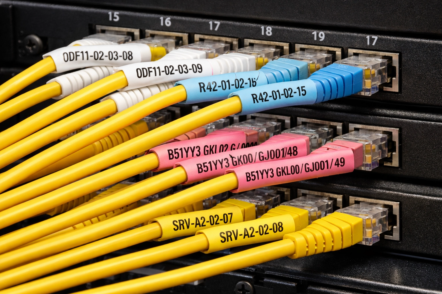
The image above demonstrates the use of standardized, color-coded wraparound labels (white, blue, pink, and yellow) combined with precise alphanumeric tagging and orderly cable routing to provide rapid visual identification and reduce human error during network maintenance and troubleshooting.
Durability is another often overlooked factor. Labels need to remain readable throughout the equipment’s entire lifecycle. When labels fade, peel off, or become illegible, the environment effectively loses its reference system, forcing teams to rely on manual tracing. A structured, durable labeling approach ensures that identification remains consistent regardless of who is performing the work.
Color coding and routing conventions
While labeling provides precision, color coding and routing conventions provide clarity in the environment. The use of a consistent color-coding scheme allows operators to rapidly and efficiently distinguish between different types of connections and cables, such as separate network tiers, redundant paths, and power cables. These features become valuable during time-sensitive situations, where quick visual cues can reduce the need for detailed verification.
The Telecommunications Industry Association (TIA) prescribes a color-coding convention for the optical cables in the TIA-598-C standard. The standards stipulate hierarchy for identification of strands, buffer tubes, and cable jackets.
However, the effectiveness of color coding depends upon consistency. If teams apply different standards across deployments or expansions, the visual meaning breaks down, resulting in confusion and human error. For example, if teams deploy a new row using a different color scheme than the existing environment, operators can no longer rely on color to distinguish between primary and secondary paths.
Routing conventions play a similar role by defining how teams physically organize cables as they route them through racks and pathways. Implementing predictable routing patterns reduces visual clutter and makes it easier to follow connections logically, even in dense environments. Overall, color coding and routing conventions together reduce cognitive load and improve the speed at which operators can understand the environment.
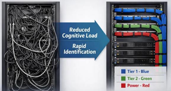
The illustration above contrasts a disorganized cabling environment with one that implements rigorous color coding and routing conventions. The transition to standardized practices, such as using blue for Tier 1, green for Tier 2, and red for power, enables rapid identification and reduces cognitive load, significantly enhancing operational efficiency and reliability.
Standard enforcement
The effectiveness of standardization depends on enforcement. Teams should embed standards in how they execute work, not treat them as optional guidelines. Also, teams should incorporate standards into installation requirements, validate them during commissioning, and reinforce them during operational changes.
Teams should incorporate standards into:
- Installation guidelines and contractor requirements
- Validation processes during commissioning
- Ongoing compliance checks during operational changes
In practice, small deviations that teams never corrected cause most long-term issues. A cable routed outside of a designated pathway or a labeling shortcut taken during a time-constrained installation may seem insignificant in isolation, but as these exceptions accumulate, they reduce the environment’s consistency. Over time, this leads to a state in which standards exist on paper, but teams no longer reflect them in practice. Enforcement mechanisms ensure that standards remain active controls rather than passive documentation. Over time, this preserves consistency across the environment and supports reliable day-to-day operations.
Physical segregation
Physical segregation dictates how different types of infrastructure are physically separated and organized inside the data center. It is less about neatness and more about ensuring that independent systems remain independent under live operating conditions. At a high level, segregation ensures that the physical layout reflects the environment’s intended design. Redundancy, fault tolerance, and domain boundaries are only effective if they are maintained not just logically but physically.
Domain separation
Different infrastructure domains, such as power and data, should follow clearly separated physical paths. This separation reduces the likelihood of interference and prevents unrelated systems from being affected by the same physical disturbance.
Teams must also appropriately separate multiple redundant connections. It is common to see logically redundant paths routed through the same cable tray or conduit for convenience, but this creates a shared point of exposure. A single disruption, whether accidental or environmental, can affect both paths simultaneously, leading to a complete outage if both the primary and redundant paths are lost. Maintaining separation at the physical layer ensures that redundancy behaves as designed during failures.
Pathway architecture
Teams implement segregation through pathway design, which includes choices such as overhead versus underfloor cable routing and how cables are distributed vertically and horizontally through conduits or rack cable management trays. Each approach has its own pros and cons. Underfloor pathways make the server room look clean and tidy, but they can become constrained over time as teams consume capacity. Overhead trays are more visible and easier to audit, but require careful planning to avoid congestion and can become heavy as capacity increases.
Overall, the key is not which approach teams choose but how consistently they apply it. Teams should design pathways with long-term capacity in mind. As environments grow, ad hoc routing becomes more common when pathways are not clearly defined or have reached their limits, leading to mixed routing patterns and making the environment harder to interpret and maintain.
Density also plays a vital role. Overfilled trays not only make cable management difficult but can also introduce structural and thermal concerns. Sagging trays, restricted airflow, and limited space for future expansion all indicate that the pathway design no longer meets operational requirements.

Source (Graphical Networks)
Fault containment
A structured layout also helps minimize how far a physical issue can extend. In environments where cables are densely packed and unorganized, a disturbance in one area can easily extend beyond its point of origin. This is especially true when multiple systems share the same pathways, trays, or routing points without clear segmentation. For example, movement in a large cable bundle within a single rack can unintentionally affect connections in neighboring racks if routing is not segmented. Similarly, shared pathways across multiple systems increase the likelihood that a single point of failure will affect multiple services.
Segmentation helps reduce this exposure by containing issues within discrete areas, also called fault-tolerant domains. It ensures that when something does go wrong, the impact remains localized and easier to manage. Teams achieve effective fault containment by introducing physical boundaries within the cabling architecture, such as segregating pathways by function or redundancy group, avoiding shared routing for independent systems, and distributing connections across multiple trays or routes rather than concentrating them in a single path.
Another aspect to consider is the maintenance activities performed by technicians who frequently interact with the data center’s physical infrastructure and cabling. If routing is not properly segmented, work in one area can introduce issues into an unrelated system simply due to proximity and cable congestion.
Mechanical integrity
Once pathways and segregation are defined, attention shifts to the physical handling of cables within that structure. Mechanical integrity ensures that connections continue to perform as expected over their expected lifetime, not just at the point of installation. Unlike visible layout decisions, mechanical issues often develop silently or get caught after the cables are run and installed. A connection may pass initial testing but degrade gradually due to physical stress, only surfacing later as intermittent faults that are difficult to diagnose, or may fail when the hardware is powered on.
Bend radius and strain control
Every cable type has defined mechanical limits, particularly for bend radius and tension. Exceeding these limits does not always result in immediate failure, but it introduces stress that can affect performance over time. Fiber is especially sensitive. A tight bend behind a switch, patch panel, or in the cable tray may not trigger alarms during installation, but under sustained load, it can cause signal loss or instability and, over time, complete failure. The same can happen due to mishandling of the fiber cable during installation, which can damage the fiber core. These issues are often misattributed to hardware or network conditions when the root cause is physical.
Strain at termination points is another common issue. Cables pulled too tightly into ports or panels place continuous stress on connectors, increasing the likelihood of loosening or failure during future handling. Maintaining proper bend radius and eliminating unnecessary tension on cables ensures that connections remain stable under normal operating conditions and last for their expected lifetime. An example picture below shows a single-mode fiber cable with the recommended bend radius. Any further strain or bending of the cable during installation could result in cable damage, signal loss, and eventual failure.
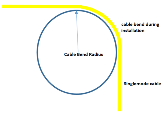
In this respect, cable slack plays a vital role. The cable slack is an intentionally added length of cable that allows for a larger bending radius and facilitates repairs and mechanical adjustments.
Structured bundling
Bundling groups of cables within pathways helps maintain structure, support accessibility, and prevent unnecessary mechanical stress. The way cables are bundled, however, has a direct impact on both performance and maintainability. Poor bundling practices often prioritize appearance over function.
Cables that are tightly compressed to reduce visual clutter introduce multiple downstream issues. Compressing cables together to keep them out of the way creates many downstream issues and can deform cable geometry, particularly in copper, thereby affecting performance characteristics. In fiber optics cables, excessive pressure can introduce microbending, which degrades signal quality without visible damage.
Bundle sizing is another significant factor. Oversized and unmanaged bundles become difficult to work with during changes. Accessing a single cable may require disturbing multiple adjacent cables, increasing the chances of unintended impact. Smaller, well-organized bundles reduce this risk by maintaining separation within the group.
The fastening method also matters. Rigid ties can create fixed pressure points that do not accommodate movement or thermal expansion. Over time, this can lead to localized stress and cable wear. Flexible fastening approaches allow bundles to remain organized while accommodating minor shifts during operational activity.
Routing within bundles should also follow a defined structure. Mixing different cable types or unrelated connections within the same bundle increases complexity during troubleshooting and modifications. Organized grouping based on function, destination, or pathway makes it easier to isolate and work on specific connections without affecting other systems.
Well-structured bundling strikes a balance between organization and flexibility, maintaining order without restricting access or introducing additional stress on the system.
In modern high‑density data center fabrics, enabling parallel optics (e.g., 4×10G, 4×25G, 10×10G) while minimizing rack space and patching complexity, on-site engineers use MPO/MTP multi‑fiber systems and fan-out breakout assemblies. Successful deployments hinge on strict polarity and pinning discipline, correct MTP gender alignment, and the use of factory‑preterminated, factory‑tested trunks or cassettes to control insertion loss across multiple lanes. Expect slightly higher IL per mate compared with single‑fiber LC connections, so design with conservative loss budgets, maintain meticulous connector cleaning, and test each lane end‑to‑end with MPO‑capable OLTS equipment.
Physical stress over time
Mechanical integrity is not a one-time consideration during the cable installation phase; it also encompasses handling throughout the lifecycle.
Cables are moved, adjusted, and rerouted during routine changes in live environments. Each interaction introduces a small amount of wear, particularly at connection points and within dense bundles. Connectors may become slightly loose, cables may settle into tighter bends, and previously well-aligned routing may shift. These changes often go unnoticed until they start affecting performance due to gradually weakened physical stability, such as accumulating link errors, link flaps, or latency issues.
Environmental conditions further influence long-term behavior. Temperature fluctuations cause expansion and contraction, which, when combined with rigid bundling or tight routing, add to mechanical stress over time. What makes these issues challenging is that they rarely result in immediate failures. Instead, they manifest as intermittent or degraded performance, making root cause identification more difficult. Maintaining mechanical integrity, therefore, requires ongoing awareness. It is not enough to install cables correctly; the environment must also support their stability over time, even as changes are introduced.
One of the trends enabling easier management of the fiber is the use of Air-blown fiber (ABF). In this method, microducts are initially installed, facilitating the easier insertion of fiber bundles into them using compressed air or nitrogen. In this way, the need to manipulate the heavy cables is reduced, resulting in lower stress on the fiber. Also, future fiber upgrades are eased.
To evaluate the health status of the fiber, the Optical Time Domain Reflectometer (OTDR) is often used by personnel on-site for recording. The readings include capturing and analyzing light reflections by creating a trace map of signal power versus distance and connectors. A good practice is to always clean the OTDR port and the cable connectors with professional dedicated cleaning wipes before the testing to mitigate the mapping of a false measurement.
Documentation accuracy
As physical infrastructure becomes more structured, the next requirement is an equally reliable representation of that structure in records. Without accurate documentation, even well-organized environments struggle to run routine operations, as decision-making relies on a reliable understanding of actual connectivity.
Documentation serves as the bridge between the physical layer and operational workflows. It allows teams to interpret how systems are connected without directly interacting with the infrastructure. When that representation is incomplete or outdated, the physical state of the environment must be rediscovered during each task, increasing time, effort, and risk.
Real-state representation
Effective documentation reflects the current state of the environment, not its intended design or past configuration. In practice, this means capturing actual port-to-port relationships, intermediate connection points, and the paths that circuits traverse through the infrastructure. Static diagrams or fragmented records often fail to maintain this level of accuracy over time, particularly in high-paced environments with frequent changes.
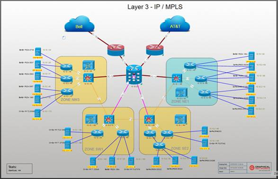
Another common challenge is fragmented documentation, such as spreadsheets, diagrams, and informal notes maintained by different teams. These quickly diverge, creating uncertainty about which version reflects reality. A single, structured representation of connectivity eliminates this ambiguity. It ensures that all stakeholders reference the same dataset of physical-state vs. logical-state records when troubleshooting, planning changes, or validating configurations. Tools such as NetTerrain provide a real-time view of connectivity by mapping circuits across devices, ports, and intermediate connection points. The graphic depicts the relationship between infrastructure components and tier paths.
Update discipline
Accuracy is not achieved through initial documentation efforts alone; it depends on how consistently records are updated and maintained during ongoing operations. Every physical change, whether it involves adding a connection, relocating a circuit, or adding/removing infrastructure, alters the state of the environment. If teams do not reflect these changes in documentation as they occur, discrepancies begin to accumulate.
That is why embedding documentation updates into the change process is essential. The change process also includes recording modifications during change execution, verifying the updated state upon completion, and ensuring that documentation reflects the final operational condition. Without this discipline, documentation gradually loses relevance. Over time, teams begin to rely less on recorded data and more on manual verification, which introduces inefficiency and increases risk and impact during critical operations.
Operational confidence
The primary value of accurate documentation is the confidence it provides during execution. When connectivity is well-defined and trusted, teams can plan and execute tasks with a clear understanding of dependencies and blockers. That approach reduces hesitation during maintenance and allows for more precise troubleshooting when issues arise. Also, when large-scale events occur, teams can jump right into the action zone and perform their tasks without wasting time studying the environment.
In contrast, when documentation cannot be relied upon, even simple tasks require additional validation. Teams may need to trace connections manually or perform exploratory actions to confirm assumptions. This tracing not only increases the time required to complete tasks but also raises the likelihood of unintended impact. For example, during a high-severity incident, the absence of reliable records may force engineers to physically trace connections across racks and patch panels to confirm circuit paths. This delays resolution and shifts effort away from addressing the root cause. Accurate documentation removes this uncertainty, allows teams to operate with clarity, reduces dependence on manual verification, and supports more predictable outcomes in both routine and high-pressure scenarios.
Capacity awareness and change integration
Once connectivity is clearly understood and trusted, the focus shifts to how the environment evolves. Physical infrastructure in a fast-paced data center environment is continually changing as technology evolves and new equipment is added. Along with that come new connections, modifications to existing ones, and spare capacity gradually diminishing. Without clear visibility into available capacity and a disciplined approach to change, these incremental updates can introduce constraints that are difficult to detect until they affect operations.
All cable pathways—including overhead trays, underfloor conduits, and vertical risers—have limited filling capacity. As utilization increases, available routing space becomes constrained. If teams do not actively monitor this consumption, environments eventually reach a point where structured routing is no longer possible. At this point, technicians make localized decisions based on immediate availability rather than using predetermined pathways. While these decisions may resolve short-term requirements, they introduce inconsistencies that make the environment harder to manage over time.
Maintaining awareness of pathways used helps prevent this shift from predefined, structured operations to reactive ones. This includes tracking capacity use, understanding where constraints are likely to occur, and defining thresholds that trigger expansion or redesign before reaching the limits. It is also important to consider vertical and horizontal pathways separately, as certain constraints may affect routing options even when there is room in other dimensions.
Changes in activity further complicate these challenges. Every modification—whether adding, relocating, or removing a connection—changes the environment’s physical state. These changes are often executed under time constraints, which can lead to decisions that prioritize speed over work quality and alignment with established structure. For example, when routing space is limited, a connection may be placed in the nearest available location rather than the appropriate pathway. Over time, these exceptions accumulate and gradually reshape the environment in unintended ways. Once these connections are made permanent on live devices, they cannot be changed, as any change would cause operational downtime.
Integrating capacity awareness into the change process helps mitigate this risk. Before performing any physical modifications, teams should assess the available routing space, pathway alignment, and overall distribution of connections. This activity ensures that changes do not cause drift in the environment, effectively controlling the process rather than letting it make slight changes. As environments scale, the importance of these considerations increases. Initial design assumptions rarely persist for long, especially in high-density deployments where capacity rapidly reduces. Eventually, connections may merge and traverse the same routing points, as this is the path of least resistance in the system, with no checks and balances in place. Connection merging creates choke points around which shared activity converges, with limited flexibility that becomes increasingly susceptible to future constraints.
Managing this effectively requires a lifecycle view. Capacity is not just something to be consumed; it must be governed. Expansion plans, new deployments, and routine changes all need to align with the environment’s physical limitations. By maintaining control over how capacity utilization and change executions are executed, organizations can ensure that growth remains structured, predictable, and sustainable.
Visualization and mapping
As environments scale and dependencies increase, understanding complex connectivity using documentation alone becomes increasingly difficult, even when the documentation is accurate and up to date. Visualization addresses this issue by providing a clearer understanding of connectivity in a much more accessible way.
Instead of examining disconnected segments of the infrastructure, a visualization provides a single view of how the whole system is interconnected—not just devices and ports but the path those connections take through the racks, rows, and distribution points of the data center. These connections are presented in a single model to enable understanding of the complex interrelationships without manual reconstruction.
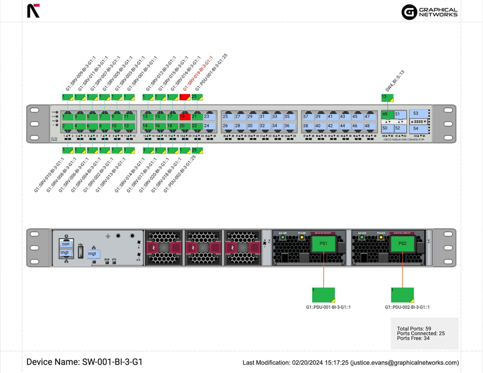
A circuit-based representation works very well. Instead of simply representing a link between two ports, the circuit is represented as a path from one endpoint to another, tracing through the intermediate connection points. This feature allows an operator to follow the logical path of a connection throughout the environment without having to cross-reference multiple diagrams or physically trace paths. It also guarantees that dependencies are included in the same representation, rather than being implied.
One of the features of modern DCIM is to allow for a Circuit Layout Record (CLR), which is a detailed end-to-end schematic representation used across IT and telecom industries. Steps to create a CLR are:
- Define the endpoints
- Trace the physical path
- Record logical attributes
- Log equipment connectors
- Generate the document
Modern DCIM and network visualization platforms, such as netTerrain, are designed around this concept. These tools model infrastructure as interconnected objects, allowing teams to visualize end-to-end connectivity in a structured and easy-to-follow format. This type of modeling shifts the focus from static diagrams to living representations of the environment.
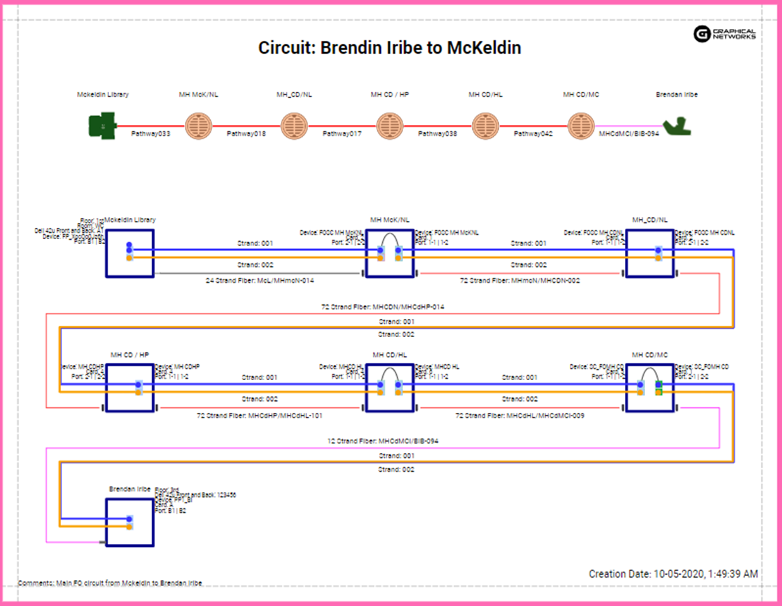
This level of visibility becomes critical while evaluating the impact of changes. A single connection may appear isolated when viewed locally, but in reality, the path it takes through other physical pathways and network resources may affect other applications. Without a clear representation of these relationships, implementing change would introduce uncertainty into overall operations. For instance, a fiber trunk might provide connectivity between multiple aggregation points across different locations in the data center. Still, when planning a maintenance activity, this information could be overlooked, and the activity might be treated as a stand-alone operation on a single physical link. When you clearly see all the dependent links that the path goes through, and the exposure associated with it, these considerations are easy to take into account.
Beyond change planning, visualization also improves troubleshooting efficiency. Once a fault is detected, an operator can clearly identify the affected circuit and trace the connection points involved, revealing potential trouble paths throughout the infrastructure. It is also useful for clearly identifying all connection points that could potentially be affected, rather than trying to figure that out through other means.
Another advantage is the ability to provide a shared operational context across teams. Network, facilities, and operations teams often work with different perspectives of the same infrastructure. A common visualization of the data center’s connections for all relevant parties fosters operational commonality and ensures that everyone has a shared understanding of those connections.
Increased complexity places equal importance on interpreting connectivity quickly and maintaining accurate records. Visualization and mapping convert structured data into actionable insight, improving operational clarity and control.
Governance and accountability
Establishing structure, maintaining accurate records, and enabling visibility are only effective if they are sustained over time. Without governance, even highly engineered environments gradually drift out of alignment due to incremental changes and the application of standards on an as-needed basis. Governance establishes how cable management practices are enforced, and accountability ensures ownership of their upkeep. Together, they prevent the environment from drifting away from its intended structure.
A common pitfall in many environments is the lack of clear ownership. Responsibilities for cabling typically span the network, facilities, and operations teams. In these situations, there are no clearly assigned ownerships, so gaps appear. Tasks such as updating connectivity records, maintaining pathway discipline, or validating compliance may be assumed to be handled by another group. When this occurs, the undocumented points drift over time, become invisible, and, in turn, make a significant impact on operations.
Establishing clear ownership removes this ambiguity. Each aspect of the physical layer, whether it is documentation accuracy, pathway management, or change validation, should have a defined responsible party, thus ensuring that standards are not only understood but also actively maintained.
Governance must also be integrated into operational workflows. Cable management cannot be a stand-alone or optional process; it must be part of the actual execution of tasks. A change, for instance, should not be deemed complete until the physical cabling is routed and labeled according to defined standards, and the documentation updated. These activities turn cable management from a post-change clean-up task into a part of the change itself.
In practice, enforcing this level of discipline benefits from having a centralized system of record. Platforms such as NetTerrain by Graphical Networks support this by providing a structured environment for tracking and consistently validating connectivity, pathways, and changes. Enforcement mechanisms play a critical role in sustaining this approach. These may include periodic audits, validation checkpoints during changes, and training to ensure consistent understanding across teams. The goal is not to introduce overhead but to ensure that standards remain aligned with actual practice.
Measurement of these practices provides visibility into how well the governance model is functioning. Many metrics are in use for cabling, such as documentation accuracy, the number of operational issues attributable to physical infrastructure errors, pathway utilization compliance, and the amount of unused/legacy cable. These metrics provide insight into the state of the physical infrastructure and the effectiveness of governance. These measurements create the final component of a feedback loop. Governance dictates execution, enforcement validates compliance, and measurement confirms that performance against governance standards is consistent over time, which allows environments to scale without structural collapse.
Some common cable-management mistakes include overfilling pathways, inadequate growth planning, poor slack/length control, mixing power and data, and weak labeling. All of the mentioned lead to airflow obstruction, difficulty moving, and an increased risk of failure. Prevent them with conservative pathway capacity planning, standardized slack templates, separate routed trays for power and data, and firm labeling and documentation standards tied to asset records. Equally critical is complete traceability for decommissioning: maintain end‑to‑end maps and test records so every cable, cassette, and port can be released cleanly. Full trace capability prevents “zombie” cables and orphaned ports, reclaims capacity safely, and eliminates hidden points of failure during migrations.
Infrastructure clarity for organizations across all industries
Conclusion
Cable management isn’t just about appearance; it’s about operational longevity and reliability. As data centers continue to scale and grow in complexity, the physical layer becomes an essential enabler of a reliable environment that supports safe changes, informed decisions, and dependable services.
The concepts discussed here, such as standardization, segregation, mechanical integrity, documentation, awareness of capacity, visibility, and governance, are interconnected. They work together to provide a context for stable, controllable, and predictable operations, helping reduce variability, increase certainty, and drive future success.
Visibility is also important. As connections become more complex and dependencies increase, it becomes critical to know precisely how, where, and what of the environment. Representations of connectivity can then be leveraged across a variety of platforms, such as netTerrain, to make more confident decisions.
Cable management is not a one-time fix; it’s a sustained practice, and when properly adopted into daily operations, it helps drive scalability.
