Effective Data Center Cooling Methods & Best Practices

As data centers grow in both number and scale, managing the heat generated by servers becomes a critical challenge. Effective data center cooling is no longer an afterthought but a fundamental design pillar that ensures equipment reliability, energy efficiency, and operational cost control.
This article provides a concise overview of data center cooling methods, introduces the most common cooling systems (including traditional air-cooling and liquid-cooling architectures) and compares their key differences. This article also provides actionable best practices for both large-scale and legacy data centers.
Summary of best practices related to data center cooling methods
The table below provides a high-level summary of the data center cooling methods and actionable best practices discussed throughout this article.
| Best practice | Description |
|---|---|
| Choose a suitable cooling system | Select a localized direct expansion system or a centralized chilled water system by considering capacity, climate zone, and expense. |
| Introduce liquid cooling for extreme loads | Transition to direct-to-chip or immersion cooling when rack densities exceed the limits of air, shifting from airflow management to liquid delivery at the rack level. |
| Implement hot aisle / cold aisle containment | Separate hot exhaust and cold intake air to eliminate mixing, improving cooling efficiency and enabling higher supply air temperatures without risking overheating. |
| Leverage economization (free cooling) | Use outside air or ambient conditions wherever possible to reduce dependence on mechanical chillers and significantly lower energy consumption and operating costs. |
| Adopt close-coupled cooling solutions | Place cooling systems near the heat source (e.g., in-row or rear-door units) to improve thermal control and handle high-density loads more effectively. |
| Use DCIM to optimize modern thermal management | Deploying extensive rack-level sensor telemetry and aggregating data within a central DCIM platform allows engineers to prevent hotspots and maintain balanced, real-time thermal control. |

netTerrain. Battle-tested & affordable DCIM Software
-

Manage data center floor plan, rackspace, cabling, power distribution, and more
-

Use analytics to optimize data center capacity and energy costs
-

Deploy quickly using asset discovery tools and pre-built integrations
Choose a suitable cooling system
Cooling systems need to maintain a recommended temperature and humidity range—typically 18-27°C (64-81°F) and 40-60% relative humidity—as defined by the American Society of Heating, Refrigerating and Air-Conditioning Engineers (ASHRAE). Beyond protecting IT equipment, efficient cooling directly impacts power usage effectiveness (PUE), a metric that compares total facility energy to IT energy. The lower the PUE, the less energy is spent on cooling and other overheads.
Typical data center cooling systems
Standard facility-level cooling relies on a multi-stage thermodynamic path to transfer heat from IT devices to the ambient environment. This infrastructure is broadly split into two key operational mechanisms: indoor heat removal and outdoor heat rejection.
Indoor heat removal: Computer room air conditioning (CRAC) vs. computer room air handler (CRAH)
At the room level, cooling units are responsible for continuously circulating air through the server:
- Computer room air conditioning (CRAC): A CRAC unit operates via a direct expansion (DX) mechanical refrigeration cycle. It contains internal compressors and uses an internal refrigerant loop (such as R-410A). Hot return air from the servers passes directly over a DX evaporator coil, transferring heat directly to the refrigerant, which is then pumped to external condensers. CRACs are typically deployed in smaller enterprise facilities or decentralized edge environments.
- Computer room air handler (CRAH): A CRAH unit does not contain internal compressors or refrigerant loops. Instead, it consists of variable frequency fan arrays and a chilled water coil. The coil is continuously supplied with cold water pumped from a centralized chiller plant. Because it leverages a shared, centralized water infrastructure, a CRAH configuration operates with significantly higher energy efficiency than DX-based CRAC systems.
Outdoor heat rejection: Chillers vs. adiabatic systems
Once heat is absorbed by the indoor loop, it must be rejected into the outside environment using one of these methods:
- Centralized chillers: Chiller plants utilize compressors to chill the water circulating to CRAH units. The heat extracted from this loop is then pushed out through external cooling towers or dry coolers. Usually chiller plants integrate heat exchangers, allowing the system to bypass the compressor cycle when the outdoor ambient wet-bulb temperature is low enough to cool the loop (which is called free cooling).
- Adiabatic Systems: Adiabatic cooling units reject heat by passing outside air through wet filter media or using fine water mist evaporation directly across the heat exchanger coils. The physical evaporation of water drops the dry-bulb temperature of the incoming air near to its wet-bulb limit. This provides exceptional thermal rejection efficiency and low power usage effectiveness (PUE) metrics, particularly in dry and cold climate areas.
Key considerations in choosing the right cooling method
Selecting a cooling strategy requires balancing multiple factors. Use these steps to guide your decision-making:
- Assess IT capacity: For legacy or small-scale data centers, a direct expansion system with aisle containment in room-level cooling remains cost-effective and simple. For data centers of roughly 500-2000 kW, in-row cooling with a direct-expansion system is a strong candidate. Above 2000 kW, chiller systems with water loops become necessary because they have higher energy efficiency and greater integration.
- Consider geographic climate and water availability: If the site is in a cool and dry region, free cooling via air or water economizers can slash annual PUE. In hot and humid climates, evaporative cooling (via cooling towers) helps but consumes water; dry coolers may be more sustainable. For desert areas with high dry-bulb temperatures, adiabatic or indirect evaporative cooling can be viable.
- Evaluate total cost of ownership (TCO), not just capital expense: When a data center scales up, moving heat with water (chiller systems) becomes drastically more efficient than moving heat entirely with air (DX systems). While centralized chiller-based configurations require a much higher upfront capital expenditure (CapEx) than simpler DX systems, they operate with drastically lower day-to-day operating expenses (OpEx) because they consume far less fan power and utilize free cooling from outside air. To cool a large data hall, a DX system has to blast massive volumes of chilled air. Because air is a poor conductor of heat (low density), DX units require high-horsepower fans spinning at maximum speeds to push enough air volume to keep servers cool. At the same time, in a standard DX system, the mechanical compressor must turn on and consume electricity whenever cooling is needed, regardless of whether it is a hot summer day or a freezing winter night. It has no way to leverage the outside weather passively. A centralized chiller system, however, can be integrated with a plate-and-frame heat exchanger to achieve water-side economization, commonly known as “free cooling.”
- Plan for future growth: If a data center is to be delivered in several phases, consider both the investment and construction complexity. It is far cheaper and more construction-friendly to install water distribution piping (even if not initially used) than to retrofit the loop later.
- Be sure to meet regulatory and sustainability goals: Many jurisdictions are tightening energy efficiency mandates (e.g., the EU’s Energy Efficiency Directive). Some companies also target a lower carbon footprint and zero water consumption. Liquid cooling and free cooling help lower carbon emissions and water usage.
Introduce liquid cooling for extreme loads
Historically, data center cooling operated as a facility subsystem, usually cooling IT devices by maintaining a steady ambient temperature for servers and network devices across the environment. However, the recent explosion of AI, high-performance computing (HPC), and dense GPU deployments has pushed contemporary rack loads well beyond 30 kW, with specialized AI clusters exceeding 50 kW to 100 kW per cabinet. Traditional air cooling methods cannot satisfy high density racks, so as cooling in data centers shifts from a facility subsystem to a system-level constraint driven by rack density growth and energy limits, liquid cooling systems are increasingly being used to cool servers.
Direct-to-chip (cold plate) cooling
This is a hybrid method that delivers liquid directly to the hottest components while leaving other components to traditional air circulation. Specially engineered copper cold plates are mounted directly onto the CPUs and GPUs, then a localized secondary loop pumps coolant directly through these cold plates. The coolant absorbs the concentrated heat at the silicon junction and is routed out of the server chassis to a coolant distribution unit (CDU). The CDU utilizes a liquid-to-liquid heat exchanger to reject heat to a water loop routed to centralized plants.
Immersion cooling
Immersion cooling completely eliminates air-cooling paths by directly submerging unsealed server hardware directly into a deep tank of non-conductive dielectric fluid. The fluid used is completely different from regular water. In traditional air cooling, it relies on fans to blow chilled air across heated metal heat sinks. In immersion cooling, it removes heat entirely by fluid; the heat conductivity of fluid is better than air, so immersion cooling is more efficient than air-based cooling and better supports high-density deployments. Because this liquid does not conduct electricity, it flows across the circuitry, RAM, and processors without causing short circuits, absorbing heat directly from the source.
There are two varieties of immersion cooling methods here:
- Single-phase immersion: Hardware is completely submerged in a bath of non-conductive fluid, and the fluid never changes its physical form—it never boils or evaporates. The fluid absorbs heat through direct contact with all components and is then driven by pumps through an external heat exchanger to exhaust heat. Once cooled, the fluid is circulated back to the tank.
- Two-phase immersion: Servers are submerged in a fluid with a low boiling point. When the IT load spikes, the processors get hot; because the fluid’s boiling point is low, the liquid boils and transitions into a vapor state. Then the vapor carries the heat up to the top of the sealed tank and is cooled by a secondary water facility loop, then condenses back into liquid form and drips back to the server cabinet.
Implement hot aisle / cold aisle containment
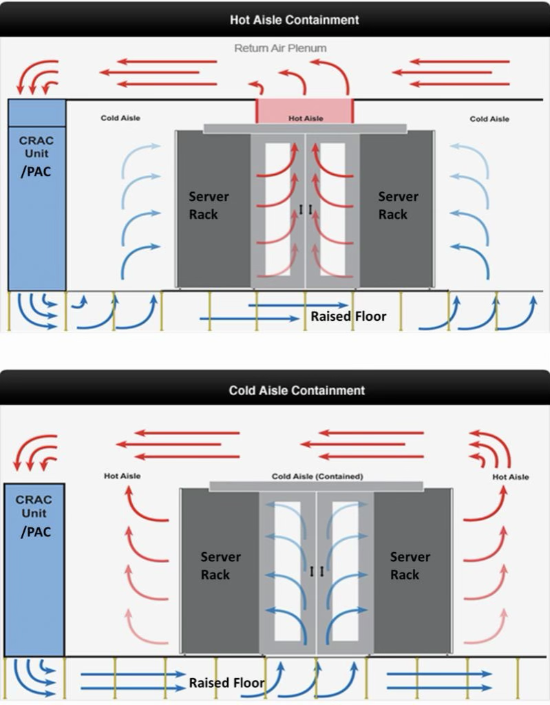
Thermal mixing is the single largest driver of operational inefficiency in traditional data centers. Implementing aisle containment isolates these streams to optimize air pressure boundaries and allow facilities to raise supply-air setpoints safely. When hot and cold air paths mix, the temperature of the air returning to the cooling units drops, lowering the cooling coil’s thermodynamic efficiency. Conversely, separating these streams maximizes the temperature differential across the cooling units, allowing them to operate at peak capacity.
Here are some implementation steps:
- Build physical containment barriers: Install rigid structural partitions, plexiglass ceilings, or automatic sliding doors to isolate either the hot exhaust aisle or the cold supply aisle. For raised-floor environments, cold-aisle containment is typically preferred to trap supply air. For slab environments, hot-aisle containment is advantageous as it captures high-temperature exhaust and routes it directly into suspended ceiling plenums.
- Enforce blanking panel compliance: Enforce strict operational rules requiring blanking panels in all empty vertical “U” spaces within equipment racks. An unsealed 1U gap can allow up to 100 CFM of hot exhaust air to short-circuit back to the server intake, creating localized hot spots despite low overall room temperatures.
- Seal cable cutouts and structural leaks: Utilize specialized brush grommets, foam seals, or gaskets to eliminate bypass air leaks traveling through floor cable tiles, structural partitions, or rack gaps. Sealing under-floor cable cutouts ensures that static pressure inside the plenum is maintained, forcing chilled air precisely where it is needed through perforated tiles.
Leverage economization (free cooling)
Relying entirely on mechanical compressor refrigeration year-round drastically inflates operating expenses. Economization processes exploit external weather conditions to passively cool internal loops. By bypassing the energy-intensive compressor cycle, facilities can drastically reduce their chiller plant power consumption.
Configure systems for air-side economization (direct cooling with outside air) or water-side economization (using dry coolers or cooling towers to cool the chilled water loop directly), depending on the geographical zone. Air-side economization works exceptionally well in temperate, clean environments but requires advanced filtration to prevent particulate contamination. Water-side economization is highly resilient and isolates the indoor air entirely from outdoor elements.
Design automation logic to allow for partial or hybrid economization modes. During intermediate seasons, outside air may not be cold enough to handle the entire heat load, but it can pre-cool the returning water loop, reducing the load on mechanical compressors rather than running them at full capacity.
Safely expand free-cooling operational hours by widening allowable temperature and humidity bounds to match the latest ASHRAE thermal guidelines (permitting upper bounds up to 27°C / 80.6°F for standard classes). Modern server hardware is highly resilient; raising the supply air temperature slightly from legacy thresholds (e.g., 22-25°C) can add hundreds of free-cooling hours per year, depending on geographical location.
Adopt close-coupled cooling solutions
Close-coupled cooling improves efficiency by placing cooling directly at the heat source, reducing airflow distance and eliminating mixing. For a small-scale data center used by the enterprise itself, building a chiller system would be a large investment and a low operating efficiency choice, making in-row cooling a better option. For scattered high density racks, rear-door heat exchangers can be used to deploy selectively rather than add cooling capacity in the entire data hall.
In-row cooling for enterprise server rooms
To implement this approach, cooling units are placed directly between server racks. In‑row cooling units draw hot exhausted air from the hot aisle, cool it using a direct expansion refrigerant circuit, and discharge cold air into the cold aisle just inches away from server intakes. Each cooling unit can handle 20-60 kW cooling requirements covering 2-6 racks, and this approach shortens the distance between the heat source, thus cutting energy consumption. Many in‑row units are floor‑mounted and front‑serviced, making them ideal for slab‑floor server rooms or spaces with limited under‑floor plenum depth.

Rear-door heat exchangers for scattered high-density racks
When an enterprise needs to deploy a few isolated, high density racks (such as 20~30kW racks running specialized AI cluster, intensive GPU nodes) scattered across rows of traditional, low density racks (such as standard 5~10kW legacy storage or network racks), it is incredibly inefficient to upgrade the cooling infrastructure or lower the supply air setpoint for the entire data hall just to satisfy a few high-output racks. Installing rear-door heat exchangers (RDHx) solves this bottleneck by deploying liquid-cooled or passive radiator doors directly onto the back of high-output server racks.
RDHx units absorb heat directly from server exhaust fans before the air exits into the room. Because the air leaves the rear door at or near the ambient room temperature, the server rack becomes thermally neutral to the rest of the room. This precise localization allows engineering teams to selectively deploy high-density workloads in legacy, low-density data halls without altering the entire room’s air distribution architecture.

Use DCIM to optimize modern thermal management
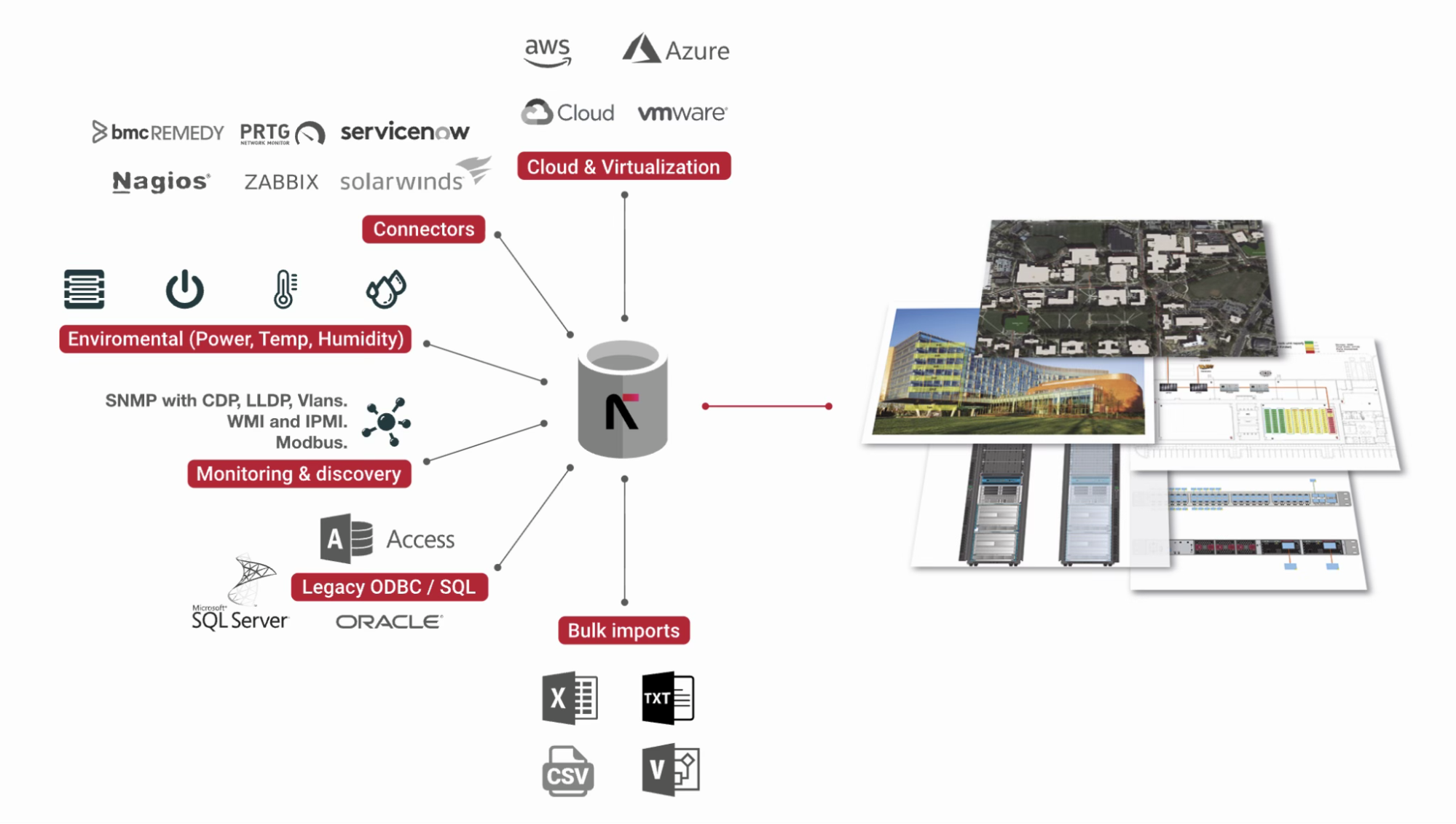
Effective cooling requires continuous visibility into how heat actually behaves inside the data hall. Environmental dynamics shift as server compute utilization fluctuates, creating an operational gap between the facility’s cooling plant and the IT equipment’s variable heat output. Data center infrastructure management (DCIM) software can bridge the gap between IT load and cooling and be invisible until a thermal incident occurs. DCIM aggregates real‑time data from two sources: server‑internal telemetry (intake temperatures, fan speeds, and power draw) and facility sensors (rack‑level temperature/humidity, CRAH supply air, and liquid loop conditions). By presenting this unified view, DCIM allows staff to respond quickly: where heat accumulates, which racks are approaching thermal limits.
Here are some implementation tips:
- Deploy sensors at the rack level: Position physical temperature and humidity sensors at the rack level rather than using generic room-level ambient metrics.
- Leverage server telemetry for dynamic heat mapping: Modern servers report intake air temperature via standard interfaces (IPMI, Redfish, or vendor‑specific tools). Configure DCIM to ingest this telemetry and generate live heat maps across the data hall. The heat map highlights the exact location, enabling targeted corrective actions (e.g., adjusting the floor opening, adding blanking panels, or rerouting airflow) without overcooling the entire space.
- Establish thermal alarms and trend‑based rules: Define automated alarms in DCIM based on meaningful thresholds, e.g., alert when a rack’s average intake temperature exceeds ASHRAE allowable range (18-27°C and 40-60% relative humidity) for a sustained period. Additionally, configure trend analysis, e.g., if a rack’s temperature rises consistently over 10°C in 15 minutes, the system alarms a potential airflow obstruction.
- Integrate DCIM with facility controls for adjustment: For organizations with mature operational integration, DCIM can communicate with the building management system (BMS) or cooling unit controllers. When server intake temperatures drop below the setpoint, DCIM can request the CRAH or CRAC lower its supply air temperature, without human intervention. This step requires API integration and safety limits, but it delivers the lowest possible PUE while maintaining thermal safety.

Infrastructure clarity for organizations across all industries
Conclusion: The integrated path to thermal efficiency
Selecting and managing data center cooling methods is no longer a simple choice for the facility planning and operation team. It is a complex engineering balancing act dictated by escalating rack densities, local water accessibility, power availability, and strict carbon footprint targets. An effective cooling strategy requires tight integration across facility infrastructure, IT equipment, and visibility software.
To achieve sustainable thermal efficiency, modern facilities should follow a progressive framework. Start with airflow isolation, maximize climate-optimized economization, bring cooling closer to heat sources, and adopt liquid cooling when density exceeds air-cooling limits.
Ultimately, the operational success of any cooling strategy depends entirely on holistic system integration. By collecting comprehensive thermal data and leveraging automated visibility and analytical controls through DCIM software, modern data centers can protect critical equipment investments, prevent thermal bottlenecks, and achieve high operational efficiency targets.
