Data Center Power Distribution: Tutorial & Best Practices
Data centers are the bedrocks of the modern economy, and due to their use by different businesses, their means of implementation vary widely. Some are owned by the data user (enterprise data centers), some are leased as a space (colocation data centers), some run as a service via cloud (hyperscale and cloud implementation), while others are used for edge computing (close to the user or located at a specific point of interest).
The rise in the use of machine learning (ML) and artificial intelligence (AI) necessitates new approaches to data center power management, ultimately enabling new ways to meet future power requirements. Regardless of data center type or size—which can range from a few tens of kilowatts to gigawatt scale—the common denominator is the existence of electrical power distribution paths in all of them.
In this article, you will find best practices associated with the design and operation of electrical power distribution systems in data centers to meet modern scalability, flexibility, resilience, and efficiency challenges.
Summary of data center power distribution best practices
| Best practice | Description |
|---|---|
| Plan for both present and future requirements | Consider the current power capacity of IT equipment along with projected capacity requirements and expansion plans. |
| Define a suitable electrical architecture | It is essential to conduct a full electrical powertrain design from the grid to the chip, including redundancy for critical facility resiliency. |
| Specify appropriate power equipment | Major power distribution components—such as transformers, UPS, distribution units, and backup generators—need to be carefully selected, designed, implemented, and maintained without interruption. |
| Develop a maintenance plan | A good maintenance system significantly improves overall facility uptime. |
| Implement components with active monitoring | Active monitoring enables real-time data gathering from critical components, enabling higher efficiency and better facility uptime while reducing costs. |
| Use DCIM software for planning | Implementing a software-based platform for infrastructure management enables traceability of components and activities through active reporting. |
netTerrain. Battle-tested & affordable DCIM Software
-

Manage data center floor plan, rackspace, cabling, power distribution, and more
-

Use analytics to optimize data center capacity and energy costs
-

Deploy quickly using asset discovery tools and pre-built integrations
Plan for both present and future requirements
All buildouts start with design, but before the design can commence, it is important to know (or at least estimate) the electrical load size of individual components, subsystems, and systems. In addition to power requirements, it is important to manage floor space tightly and plan its use to optimize costs on the operator’s balance sheet. The floor plan and IT loads affect power distribution dimensioning; if not flexible enough, they will become bottlenecks in the future, stalling growth, or become too complex to operate efficiently.
To illustrate, expanding the IT load might not be possible due to limitations imposed by upstream components, such as a transformer or a molded-case circuit breaker (MCCB). Replacing this sort of component could be very costly and might jeopardize the entire site’s operation. Paying attention to the current state and future requirements is key.
Some of the specific best practices in planning are as follows:
- Design for modular scalability: Implement modular systems and components that can easily be expanded as demand grows.
- Include capacity headroom in critical systems: Plan for major monolithic equipment, like transformers and generators, to be rated for the “end-day” (or final stage) with 10-20% of spare capacity on top.
- Reserve physical space for future equipment: Allocate floor space for future expansions and extra pathways for the end day.
- Provide expandable power and cable pathways: Oversize cable trays, busways and conduits to allow for additional power distribution pathways.
- Anticipate technology evolution and higher power densities: Think about increases in the rack power densities and how they will affect power requirements.
- Use phased infrastructure deployment: Instead of building the entire data center at once, consider deployment in phases; as soon as each phase is deployed, it can be populated to bring in revenue.
Define a suitable electrical architecture
Distribution systems must comply with mandatory regulations and standards that depend on the data center’s physical location. For example, in North America, electrical power distribution units must comply with UL and ANSI standards, whereas in Europe, they must comply with IEC standards. These regulations, standards, and norms specify the voltage levels to be used, particularly in the low-voltage domain governing the last mile of power delivery.
Power connection and grid voltage levels
Power distribution to the IT load starts with a connection to the power grid. Depending on the data center size and location, the owner will need to agree with the grid operator on the appropriate voltage level for the power connection.
The table below lists some typical grid voltage levels and suitable data center sizes.
| Voltage Level | Typical Voltage Range | Data Center Power Capacity (MW) | Typical Data Center Size/Type |
|---|---|---|---|
| Low Voltage (LV) | < 1 kV (IEC); < 600V (ANSI/NEC) | Internal distribution only; not typically a utility connection point | Small IT closets, edge computing (internal distribution) |
| Medium Voltage (MV) | 1 kV – 35 kV (IEC); 601V – 69 kV (ANSI/NEC) | 1-50 MW | Small to large enterprise data centers, colocation facilities |
| High Voltage (HV) | > 35 kV (IEC); > 69 kV (ANSI/NEC) | 50 MW – 1 GW + | Hyperscale data centers, large cloud providers, AI facilities |
Since the common electrical connection point to the IT racks is at LV, the energy must be stepped down to the appropriate level, depending on the rack configuration. In the following table, various low-voltage levels are presented in relation to wiring and key characteristics.
| Standard | Common Voltage Levels (Phase-to-Neutral / Phase-to-Phase) | Typical Wiring Configuration | Number of Phases | Key Characteristics in Data Centers |
|---|---|---|---|---|
| IEC (International) | 230V / 400V | Three-phase Wye (Star) | Single-phase and Three-phase |
|
| IEC-derived (North America) | 240V / 415V | Three-phase Wye (Star) | Single-phase and Three-phase |
|
| UL (North America) | 120V / 208V 277V / 480V | Three-phase Wye | Single-phase and Three-phase |
|
Emerging architectures for high-density racks equipped with GPUs for AI-intensive workloads are also exploring 800V DC to improve efficiency.
Some of the best practices for choosing the voltage level are following:
- Use higher voltage levels: Higher voltage levels reduce currents and thus power losses as well as reducing the use of copper due to a reduction in cable cross-sections.
- Minimize the number of voltage transformations: Reduce the number of voltage levels in the facility to reduce losses.
- Standardize voltage across the facility: Once you select a voltage level, keep it consistent throughout the facility to optimize spare part management and simplify maintenance procedures.
- Consider regional grid voltages: Align internal voltage levels with local regulations and standards.
- Evaluate fault levels: Choose a voltage level that allows for the easy implementation of protection components and protection coordination.
Power distribution paths
To ensure the resilience of a critical facility such as a data center, it is paramount to create redundant power distribution paths to achieve high uptime. Some of these principles are governed by standards set by organizations such as the Uptime Institute, BICSI, and EN 50600, while some architectures are not strictly aligned with these standards but still provide significant facility resilience.

The choice of topology ultimately affects how maintenance will be carried out and determines the system’s resilience in the event of failures. Various architectures consist of multiple, often redundant distribution pathways and include components such as transformers, power cables, automatic transfer switches (ATS), backup generators, uninterruptible power supplies (UPS), and distribution units equipped with circuit breakers.
Data resilience tiers
Resilience of critical infrastructure, such as data centers, is paramount and must be built into both the design and facility operations. Globally, standards and advisory services are structured around resilience and, often as a reference, draw on frameworks from reputable authorities such as Uptime Institute and BICSI. These authorities are well established in the data center industry and can provide guidance on structuring different levels of resilience for data centers, as well as conduct audits and certifications. In addition to these, the EN 50600 standard prescribes similar requirements, but the main difference is that the advisory and auditing are provided by certified third parties.
The most common reference in the industry is prescribed by the Uptime Institute, where they structure different resiliency levels as “tiers.” The table below presents an overview of the different tier levels.
| Feature | Tier I: Basic Capacity | Tier II: Redundant Components | Tier III: Concurrently Maintainable | Tier IV: Fault Tolerant |
|---|---|---|---|---|
| Uptime Guarantee | 99.671% | 99.741% | 99.982% | 99.995% |
| Annual Downtime | 28.8 hours | 22 hours | 1.6 hours | 26.3 minutes |
| Power Path | Single, non-redundant path | Single path with redundant components (N+1) | Multiple independent active power paths (N+1) | Multiple active independent power paths (2N or 2N+1) |
| Cooling Path | Single, non-redundant path | Single path with redundant components (N+1) | Multiple independent active cooling paths (N+1) | Multiple active independent cooling paths (2N or 2N+1) |
| Redundancy | N (single capacity) | N+1 (redundant components) | N+1 (concurrently maintainable) | 2N or 2N+1 (fault tolerant) |
| Concurrent Maintainability | No | No | Yes (any component can be taken offline without affecting IT operations) | Yes (any component can be taken offline without affecting IT operations) |
| Fault Tolerance | No | No | No (single point of failure can still exist) | Yes (no single point of failure) |
| Compartmentalization | No | No | No | Yes (physical separation of redundant systems) |
| Maintenance Impact | Requires full shutdown of IT operations | Requires full shutdown of IT operations | Allows for planned maintenance without affecting IT operations | Allows for planned maintenance without affecting IT operations |
| Cost | Lowest | Low to Medium | Medium to High | Highest |
| Typical Application | Small businesses, non-critical operations | Small to medium enterprises, less critical applications | Large enterprises, colocation, most mission-critical applications | Financial institutions, government, critical national infrastructure |
Here’s a brief description of the impacts of tier levels on power distribution:
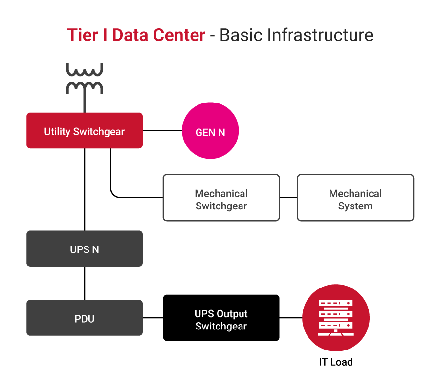
- Tier I: The most basic structure with a direct radial power distribution path, with a single generator and a single UPS or a modular UPS without redundancy (N modules, enough to cater for the load) without any redundancies.
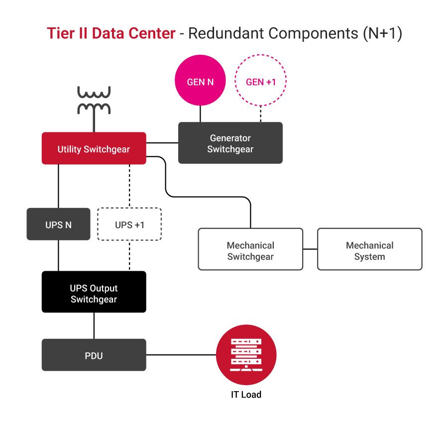
- Tier II: Basic structure with direct radial power distribution path, with generators and UPS in N+1 configuration, allowing for the increased uptime in case of a single UPS module failure.
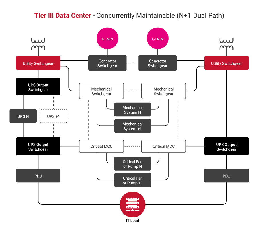
- Tier III configuration: Allows maintenance without interrupting operations. Two independent power distribution paths exist; generators and UPSs are in an N+1 configuration, where every module must be able to switch between the sources and distribution paths.
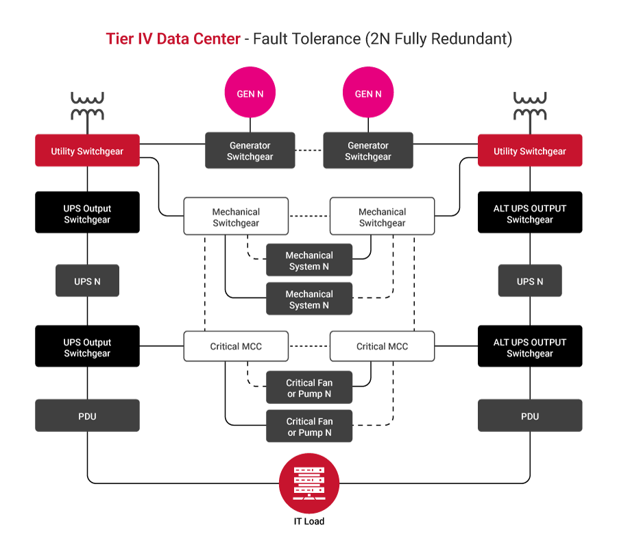
- Tier IV: A fault-tolerant structure incorporates dual distribution paths, each governed by N or N+1 generators and a UPS.
Some good practices for tier selection include the following:
- Assess business criticality: Identify which applications and services are mission-critical and quantify the financial and reputational impact of their downtime. Higher criticality generally requires a higher tier.
- Evaluate risk tolerance levels: Determine the acceptable risk level for outages. Organizations with low tolerance for downtime will lean towards Tier III or Tier IV facilities.
- Conduct a cost-benefit analysis: Compare the increased costs associated with higher tiers (in areas such as construction, maintenance, and energy) against the potential losses from downtime at lower tiers.
- Consider scalability and future growth: Choose a tier that can accommodate future expansion and evolving technology requirements without significant redesign.
- Validate tier certification: Always verify that a data center’s claimed tier level is officially certified rather than relying solely on self-declarations
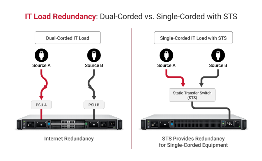
Single-corded and dual-corded loads
Dual-corded IT loads feature two independent power supplies and cords, allowing them to draw power from two separate sources for built-in redundancy. Single-corded equipment lacks this redundancy, making it vulnerable to downtime if its sole power path fails. To protect these single-corded devices, a static transfer switch (STS) is used to switch the load between two independent power sources in a near-instantaneous fashion in the event of a failure.
Good practice in the selection of the IT equipment, from an electrical connection standpoint, is to choose equipment with two (independent) inputs: the dual-corded variant. In that way, a single point of failure is avoided and the number of components used is reduced, leading to lower infrastructure costs.
Specify appropriate power equipment
HV and MV switchgear
Data center connection is often achieved at high voltage (HV) or medium voltage (MV) levels, for which special types of switchgear are used. To support sustainability, a good practice is to consider air-insulated (AIS) switchgear equipped with vacuum circuit breakers. At higher voltages, it may be necessary to consider gas-insulated (GIS) switchgear, which can extinguish electrical arcs caused by high voltage and is usually filled with SF6 gas, although new, more eco-friendly solutions are in development.
The following table describes HV and MV switchgear circuit breaker technologies.
| Feature | Vacuum | SF₆ | Oil | Air Blast |
|---|---|---|---|---|
| Voltage Range | Up to 40.5 kV s | Up to 800 kV | Up to 36 kV | Up to 800 kV |
| Maintenance | Very low | Low | High | Moderate |
| Environmental | Eco-friendly | High GWP | Oil disposal | Eco-friendly |
| Arc Interruption | Excellent | Excellent | Good | Good |
| Cost | Moderate | Moderate | Low | High |
| Typical Use | MV switchgear | MV/HV switchgear | Legacy systems | Phased out |
Transformers
Transformers are specified based on incoming and outgoing voltages as well as fault levels. Special attention is given to impedance, thermal performance, and insulation classification, as they directly affect short-circuit behavior and system stability.
The latest trend in data center applications is to use dry-type transformers wherever possible to reduce maintenance. Special attention should be given to the K-rating of the transformer, regardless of type, which is related to harmonics and is especially important for AI loads due to significant harmonic content.
| Feature | Dry-Type | Oil-Filled |
|---|---|---|
| Fire Risk | Low | Higher |
| Maintenance | Minimal | Regular oil checks |
| Efficiency | ~99% | ~99.5% |
| Noise Level | Higher | Lower |
| Cost | Higher initial | Lower initial |
| Size | Larger | More compact |
Backup generators
Traditionally, backup power was supplied exclusively by diesel generators, while today alternatives are gaining more traction. In some rare cases where the commercial electrical grid is not available or has limited availability, these technologies are even considered the primary power source, which is especially true for gas technologies. Gas-powered generators are connected directly to the natural gas pipeline, while diesel generators rely on tanks that can support a 48-72 h runtime at full load. A good practice is to use a vegetable-based oil when possible to reduce emissions and promote sustainability.
The following table compares generator technologies with pros and cons.
| Generator Type | Fuel Type | Pros | Cons | Typical Data Center Application |
|---|---|---|---|---|
| Diesel Generators | Diesel |
|
| Most common for traditional backup power in all data center tiers, especially for long-duration outages |
| Natural Gas Generators | Natural Gas |
|
| Increasingly used for backup and prime power, especially in areas with reliable gas infrastructure and stricter emission regulations |
| Gas Turbine Generators | Natural Gas, Diesel, Kerosene |
|
| Large-scale hyperscale data centers, often used for continuous power or very long-duration backup where emissions are a major concern |
Uninterruptible power supplies (UPSes)
An uninterruptible power supply is the heart of the power protection scheme and ensures the continuity and premium power quality of the power supply to the IT load. There are different types of UPSes in the market, which can be differentiated by tier build, internal topology, energy storage type, and other attributes. It is important to know which type of UPS is best suited to your specific applications, as their construction, rating, and installation methods can vary significantly. Good UPS selection practice ensures compliance with the IEC 62040-3 Class 1 standard, which is very common for the online UPS.
| Feature | Standby (Offline) UPS | Line-Interactive UPS | Online (Double-Conversion) UPS |
|---|---|---|---|
| Operation | Switches to battery when utility power fails. | The inverter is always connected to the output and regulates voltage. | Converts AC to DC, then DC to AC, continuously powering the load from the inverter. |
| Power Path | Primary: Utility AC; Backup: Battery/inverter | Primary: Utility AC (with voltage regulation); Backup: Battery/inverter | Primary: Battery/inverter (always active) |
| Transfer Time | 4-8 ms (detects outage, then switches) | 2-4 ms (detects outage, then switches) | 0 ms (no transfer, seamless) |
| Voltage Regulation | None | Automatic voltage regulation (AVR) | Continuous, precise voltage regulation |
| Power Conditioning | Basic surge protection | Basic surge protection, noise filtering | Superior (isolates load from all utility disturbances) |
| Efficiency | High (when on utility power) | High (when on utility power) | Lower (due to continuous conversion) |
| Cost | Low | Medium | High |
| Typical Applications | Home PCs, small office equipment | Small to medium-sized business servers, networking equipment | Data centers, mission-critical servers, medical equipment, and industrial applications |
| Protection Level | Basic | Good | Best |
Energy storage
The most common energy storage technology in data centers is based on valve-regulated lead-acid (VRLA) batteries, although lithium-based batteries are gaining in popularity lately. While VRLA is a well-established technology, li-ion enables a significant reduction in footprint, freeing up more real estate and improving price competitiveness, and they come with cell monitoring on board. At the same time, li-ion batteries pose a higher fire risk due to fire propagation from thermal runaways. Good practice is to consider placing li-ion batteries outside the main building to mitigate fire risk.
An alternative to electrochemical energy storage is the mechanical flywheel, which is eco-friendly and highly efficient; however, it can only provide up to 15 seconds of power, limiting the choice of on-site power generators to fast diesel generators.
New technologies, such as sodium-based technologies and flow batteries, although available, are still not widely used in the data center space.
Here’s a comparison of energy storage technologies.
| Technology | Discharge Time | Footprint | Cost | Best Use Case |
|---|---|---|---|---|
| VRLA (Lead-Acid) | 5–30 min | Large | Low | Legacy UPS systems |
| Li-ion NMC | 5–60 min | Compact | Medium | High-density UPS |
| Li-ion LFP | 5–60 min | Medium | Medium | Modern UPS (safest Li-ion) |
| LTO | 5–30 min | Medium | High | High-cycle applications |
| Sodium-ion | 10–60 min | Medium | Low-medium | Cost-sensitive deployments |
| Flow Battery | Hours | Very large | High | Long-duration storage |
| Flywheel | 15 sec–15 min | Medium | High | Bridging to the generator |
Distribution units
Power distribution units are found in data centers at all voltage levels between major components, housing circuit breakers (or, very seldom, fuses) that provide protection against short circuits and enable safe operation and maintenance. Different types are described in the table below.
| Distribution type | Typical Location | Primary Function |
|---|---|---|
| Utility Substation / Switchgear | External or just inside the facility perimeter | Steps down high-voltage from the utility; provides main-circuit protection and switching. |
| Automatic Transfer Switch (ATS) | Main electrical room / Generator enclosure | Automatically switches power source between utility and backup generators during outages and restorations. They are standalone or part of the main switchgear lineup. |
| Main Switchgear / Main Distribution Panel (MDP) | Main electrical room | Central point for distributing power to major data center systems (UPS, cooling, lighting) and providing overall circuit protection. |
| Power Distribution Unit (PDU) / Floor PDU | Data hall floor (often in rows or near IT equipment) | Distributes conditioned power from the UPS to remote power panels (RPPs) or directly to server racks; may include transformers for voltage step-down. |
| Remote Power Panel (RPP) | Data hall floor (closer to IT racks than PDUs) | Provides additional power distribution and circuit protection closer to the IT loads, often fed by a larger PDU. |
| Rack Power Distribution Unit (Rack PDU) | Inside individual server racks | Distributes power to individual servers and IT equipment within the rack; often includes monitoring and control features. |
Some of the best practices associated with distribution units are as follows:
- Balance phase loading: Distribute loads evenly across all phases to avoid uneven loading upstream.
- Coordinate protection: Ensure that all protective equipment is properly coordinated so that the fault is isolated as close as possible without interruptions to other parts of the system.
- Allow for spare capacity: Design distribution units with spare positions to allow for future expansion.
- Ensure proper cable management: Clearly label cables and make sure they are properly placed in cable glands and gutters with clear routing and without overlapping.
- Enable remote monitoring: Allow for real-time alarms and data gathering.
Develop a maintenance plan
Maintenance in a critical infrastructure facility is a fundamental need, whether a crew is on board or a third party is hired at the operator’s discretion based on their needs. Regardless, regular scheduled maintenance, also referred to as preventive maintenance, is needed to prevent interruptions and unplanned downtime. Some of the activities that need to be conducted regularly include checks of critical equipment, updating to the latest firmware, and ensuring dust removal. More sophisticated maintenance may include using thermovision to detect thermal runaways in the power system.
Traditionally, most OEMs advised up to two site visits per year by engineers for preventive maintenance and regular checks. With strong growth in automation, remote monitoring, and DCIM solutions, the number of site visits has been reduced to a single visit for most equipment.
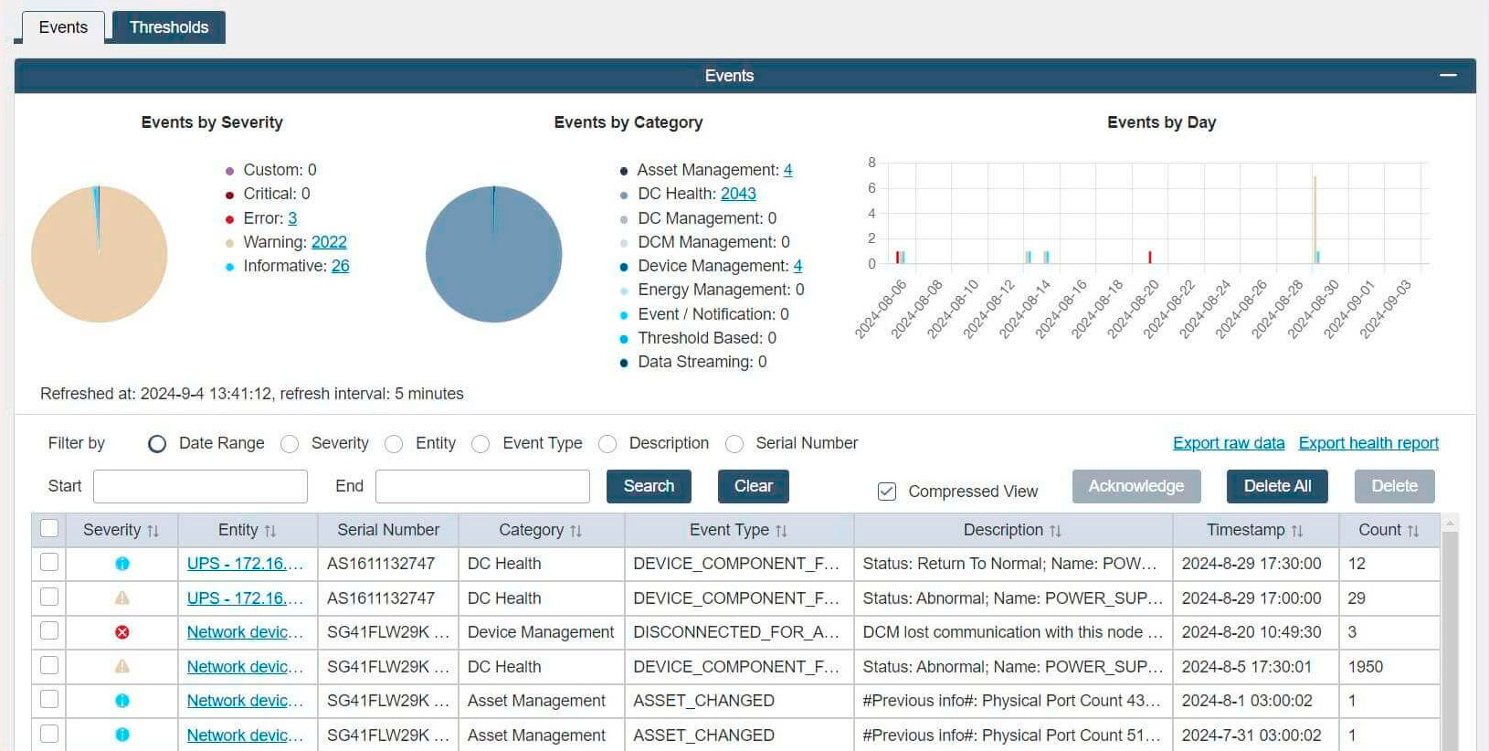
Good practice is to introduce a system that allows a comprehensive overview of all maintenance activities with easy access to the responsible personnel. An example of the event log showing events by category and date is shown in the picture below.
Some of the best practices associated with maintenance planning are as follows:
- Implement a structured maintenance program: Schedule inspections and servicing of the critical components on site, such as generators, UPS, transformers, and batteries.
- Perform regular thermographic inspection: Every six months, perform a thermographic site inspection to trace any deviations from the previous one, which could indicate abnormal behavior associated with cables, busbars, circuit breakers, or connections.
- Periodically test backup systems: Test batteries and generators, preferably using the dummy loads in the form of a load bank.
- Maintain documentation and records: Regularly update service logs and make sure there is clear traceability of all activities accessible to responsible personnel.
- Use predictive maintenance: With new generations of equipment, enable predictive maintenance to detect degradation before failure happens.
Implement components with active monitoring and control
Using so-called “smart” components, such as smart low-voltage circuit breakers with communication features and active voltage and current sensors on switchgear and transformer units, makes a dramatic difference by enabling the retrieval and storage of measured values such as voltage, current, cos phi for later analysis. These devices are typically installed in circuit breakers in distribution units and in transformers at all voltage levels of the operator-owned power network.
OEMs typically offer cloud-based solutions from which measurement results can be retrieved. An alternative is to build a proprietary supervisory control and data acquisition (SCADA) system on-site and store all data there.
In combination with preventive maintenance activities, the gathered data is analyzed to provide deeper insight into potential issues that may arise in the foreseeable future. Active monitoring also enables real-time efficiency tracking and enforcement of sustainability goals.
Here are some of the communication protocols used by power components in data centers.
| Protocol | Description | Pros | Cons |
|---|---|---|---|
| Modbus | A serial (RTU/ASCII) or Ethernet (TCP/IP) protocol for master-slave/client-server communication. Widely used in industrial automation and energy management. |
|
|
| Simple Network Management Protocol (SMNP) | An internet-standard protocol for managing devices on IP networks. Commonly used for monitoring network devices, but also for power infrastructure. |
|
|
| Building Automation and Control Network (BACnet) | A communication protocol specifically designed for building automation and control systems, including HVAC, lighting, and energy management. |
|
|
| IEC 61850 | An international standard for communication networks and systems in substations and electrical power systems. Increasingly adopted in large data centers for critical power infrastructure. |
|
|
Use DCIM software for planning
A data center infrastructure management (DCIM) system can significantly improve data center operations. Implementing these systems enables planning and operation by providing a single interface to the multiple components that collectively comprise power distribution systems. Maintaining inventory, retrieving current status information, tracking maintenance activities, and reporting are just some of the features of a high-quality DCIM. Having a flexible, scalable DCIM supports current requirements and future needs for power distribution systems.
From the perspective of power distribution operations, one of the most important parameters is efficiency, one of many that can be aggregated, calculated, and tracked via DCIM.
Power utilization factor (PUE) is one of the most widely used metrics in the industry to indicate a facility’s overall power efficiency. Originally envisioned as a matrix for tracking facilities’ efficiency over time, it is now also used to benchmark facilities. The PUE is the ratio of the total power entering the facility (including IT, cooling, lighting, and other ancillary services) to the power consumed by active IT equipment alone.

Still, most of the benefit for operators, although often overlooked, lies in the single facility’s operation and evolution over time, indicating to operators the impact that the changes they made have on overall effectiveness.
Other metrics can also be considered, such as water use effectiveness (WUE), carbon use effectiveness (CUE), and energy reuse effectiveness (ERE).


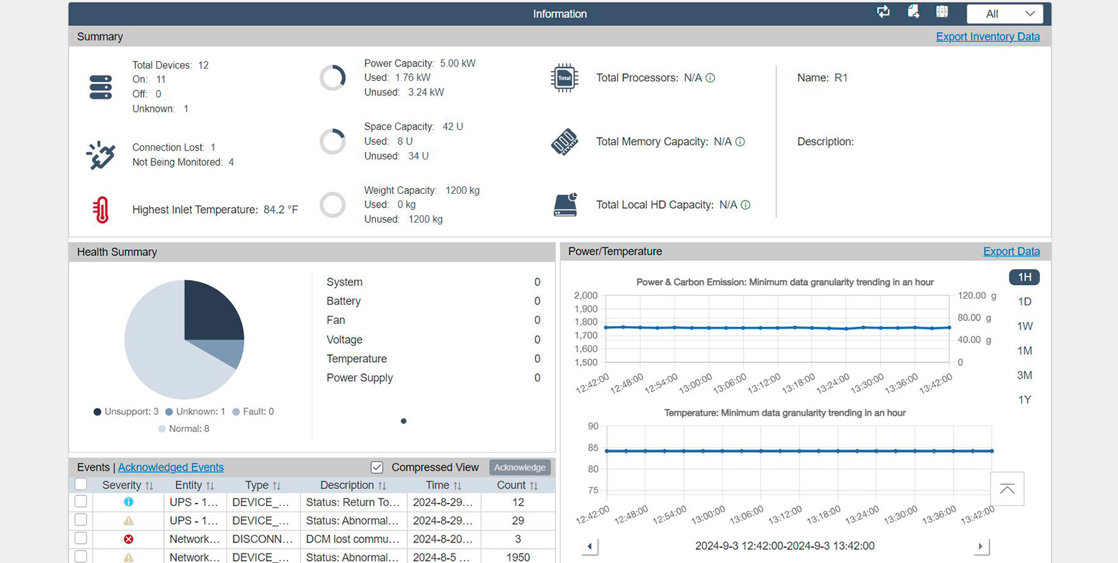
The screenshot below shows an example of live measurements, interpreted as power and carbon footprint.
To implement these metrics correctly, meticulous planning and on-site measurements are required, preferably through active monitoring and data collection.
Infrastructure clarity for organizations across all industries
Conclusion
Planning, operating, and maintaining power distribution systems in a critical facility is paramount to achieving high uptime. As data centers become more complex, it is essential to consider every component and its potential environmental impact.
Best practices for data center distribution span planning, design, implementation, operation, and maintenance. Undertaking all of these endeavors requires meticulous orchestration and attention to detail.
While each endeavor is important, their aggregation is paramount to unlocking true potential through data center infrastructure management (DCIM) software. DCIM serves as the data center’s central nervous system, providing a holistic view and actionable insights across all infrastructure layers. Implementation of a DCIM system enables optimal capacity utilization and planning, traceability of power distribution architecture, enhanced power management, and streamlined maintenance operations. These capabilities enable informed decision-making that ultimately leads to high reliability and uptime, high efficiency, optimal stock levels, and infrastructure flexibility, which, in turn, provides significant cost reductions for data center owners.