AI Data Center Design: Best Practices for Power, Cooling, and Networking

The growth of artificial intelligence (AI) is changing how data centers are designed. As large language models (LLMs), AI agents, and AI-driven enterprise applications continue to scale, traditional data center designs are increasingly challenged by demands for computing density, power delivery, cooling capacity, network connectivity, and deployment speed.
Three data center infrastructure trends are particularly important: higher rack power density, the wider adoption of liquid-cooled thermal architectures, and large-scale cluster deployment.
Recent manufacturer roadmaps and industry publications reflect these changes. NVIDIA positions 800 VDC as the next-generation power distribution architecture, designed to reduce energy loss and minimize copper and cabling volume while supporting future AI servers. ASHRAE released a white paper on servers that incorporates liquid cooling and coolant properties into the design of cooling systems. OEMs have published reference designs that combine power, cooling, and control systems and prefabricated modules rather than treating each system separately.
This article explains how AI workloads affect facility design and examines practical approaches to power, cooling, networking, modular deployment, and operation.
Summary of key AI data center design best practices
| Best practice | Description |
|---|---|
| Define the infrastructure for the AI workload | Translate AI cluster demand into facility inputs, including power, rack density, liquid heat-capture ratio, and growth assumptions. |
| Engineer the electrical system for high-density AI loads | Design the complete power chain around rack density, synchronized load swings, and long-term technology change, using NVIDIA 800V DC as a case study. |
| Create an end-to-end thermal architecture | Design the full heat path from chip to final heat rejection, coordinating cold plates, rack manifolds, CDUs, and facility water. Adopt D2C as the primary cooling strategy for its balance of performance and maintainability, reserving the rear-door heat exchanger or immersion cooling as an option based on platform and operating requirements. |
| Match the interconnect to the cluster scale | Select InfiniBand, RoCE, or high-performance fabrics based on communication patterns, latency, and bandwidth. Treat topology, switch placement, fiber pathway, and cable trench as early facility-design inputs. |
| Size pods around failure and maintenance domains | Map compute, electrical, cooling, network, and control domains to the physical pod, so credible faults and planned maintenance have a limited blast radius. Provide practical isolation, bypass, detection, response, and restoration strategies rather than employing indiscriminate redundancy. |
| Use modularity and standardization to enable repeatable growth | Define pods as repeatable capacity blocks with standardized power, cooling, network, control, and physical interfaces. Separate long-life facility infrastructure from replaceable technology modules so that capacity can be deployed in phases and refreshed without stranding the wider site. |
| Build control, monitoring, and digital visibility for operation | Connect facility, liquid cooling, IT, and network telemetry through consistent data models and actionable operating views. |

netTerrain. Battle-tested & affordable DCIM Software
-

Manage data center floor plan, rackspace, cabling, power distribution, and more
-

Use analytics to optimize data center capacity and energy costs
-

Deploy quickly using asset discovery tools and pre-built integrations
Define the infrastructure for the AI workload
What makes an AI data center different from a traditional data center?
Here are some of the key factors:
- GPU-driven compute intensity: AI workloads use accelerators (such as NVIDIA H100/Blackwell and AMD MI300X) optimized for matrix/tensor operations. This enables the massive-scale parallelism essential for billion-parameter models.
- Massive parallelism and low-latency network: Conventional server architectures primarily support general-purpose workloads and standard Ethernet connectivity. Large-scale distributed AI workloads require high-bandwidth, low-latency links to synchronize and exchange data across accelerators. Accordingly, AI data centers rely on technologies such as InfiniBand, NVLink, and RoCE (RDMA over Converged Ethernet). Scale-up architectures further extend the high-speed interconnect domain from a small number of accelerators to hundreds or even thousands, minimizing communication overhead and enabling higher performance for large-scale AI training and inference.
- High-density rack power and liquid cooling adoption: Traditional data center racks typically operate at 10-20 kW, whereas high-density AI racks can exceed 100 kW. This dramatic increase in power density fundamentally changes the design of power distribution, busways, cabling, and cooling infrastructure. As rack-level heat loads increasingly exceed the practical limits of conventional air cooling, liquid cooling is becoming the preferred approach for high-density AI deployments. Technologies such as direct-to-chip cooling and immersion cooling enable data centers to remove large thermal loads while maintaining GPU performance efficiently.
From server specification to infrastructure requirements
Project teams often begin traditional data center planning with rack count and average rack power density. For an AI data center, the team should model a continuous chain from the accelerator to the campus rather than relying on a single rack-power number. A facility team needs an explicitly defined set of infrastructure requirements for each platform generation. Instead of specifying a rack simply as “100 kW,” the design input should define steady-state and peak power, load ramp rate, input-voltage architecture, redundancy requirements, liquid heat-capture ratio, coolant type and supply-temperature range, minimum flow and differential pressure, residual air load, rack weight, network topology, cable reach, acoustic limits, service clearances, and the required response sequence following loss of power, coolant, or communications.
As an example, two racks with the same nominal power can impose very different demands on the facility. A 100 kW rack with 90% of its heat captured by liquid cooling is fundamentally different from a 100 kW rack that rejects a large fraction of its heat to air. Likewise, a rack with a relatively flat 100 kW load behaves differently from one that can ramp rapidly from 40 kW to 100 kW. These differences propagate directly into feeder sizing, cooling-loop capacity, CDU selection, air-handling requirements, control sequences, and backup-system design.
Engineer the electrical system for high-density AI loads
AI changes the electrical design in three ways:
- Rack density raises current and copper requirements.
- Synchronized workloads create fast load swings that can propagate beyond the rack.
- The useful life of the electrical plant is much longer than the computing generation it serves.
The electrical design should support the current compute platform without preventing a later move to higher-voltage distribution or higher rack densities.
Today’s typical architecture
Most existing facilities distribute medium voltage to transformers, low-voltage switchgear, UPS systems, and busways before conversion within the IT equipment. This architecture remains mature, serviceable, and supported by established protection practices. Near-term improvements to AC systems include reducing conversion stages, shortening low-voltage distribution paths, integrating energy storage more closely, and aligning modular power blocks with compute fault domains.
Centralized and distributed UPS arrangements should be compared by failure domain, maintainability, efficiency at expected loading, battery location, bypass behavior, replacement strategy and compatibility with dynamic AI loads.
The emerging frontier: 800 VDC
NVIDIA describes 800 VDC as a transition from multiple AC conversion stages toward a single AC-to-800 VDC conversion, with DC distributed through the data center and used directly by the compute rack. This approach reduces current, copper use, cable bulk, distribution losses, and conversion stages compared with rack-level 54 VDC and facility-level 480 VAC architectures.
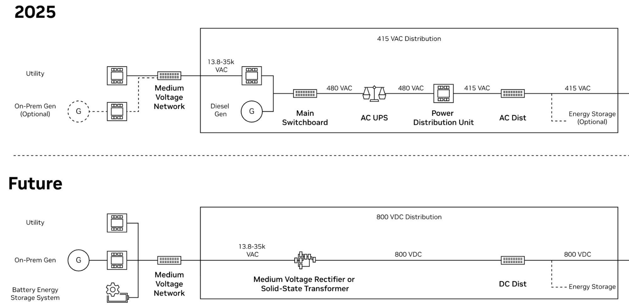
The roadmap also includes hybrid power racks intended to introduce 800 VDC into existing AC facilities. The upper half of the image above shows a modern data center: before power is converted to direct current (DC) at the computer racks, it undergoes multiple conversions between alternating current (AC) sources. The lower half shows the AI factory of the future: only a single conversion from AC to 800 VDC is required. The 800 VDC will be distributed within the data center for direct use by the computer racks.
Higher voltage carries the same power at lower current, allowing more compact conductors and distribution equipment. DC distribution can also integrate naturally with battery systems and power electronics. However, 800 VDC places greater emphasis on DC fault interruption, isolation, grounding, insulation monitoring, arc containment, and safe maintenance procedures. A deployable 800 VDC system therefore requires coordinated breakers, busways, converters, controls, and test procedures across the complete power chain.
Solid-state transformers (SST) and other medium-voltage power electronics may provide another route to reducing conversion stages and integrating storage. Their adoption will depend on efficiency across the operating range, semiconductor reliability, fault behavior, maintainability, harmonic performance, compliance with standards, and lifecycle support.
Grid interaction and energy storage
AI load behavior is becoming a campus and grid-design issue. Storage may need to perform several jobs at different timescales: ride through short transients, smooth rapid changes, support transfer, limit utility ramp rate, participate in demand management, and provide longer backup. Each function should be specified separately because it operates over a different timescale and may require different storage technology.
netTerrain recognized as “Major Player” in IDC MarketScape’s 2026 Datacenter Facilities Management Software Vendor Assessment
Create an end-to-end thermal architecture
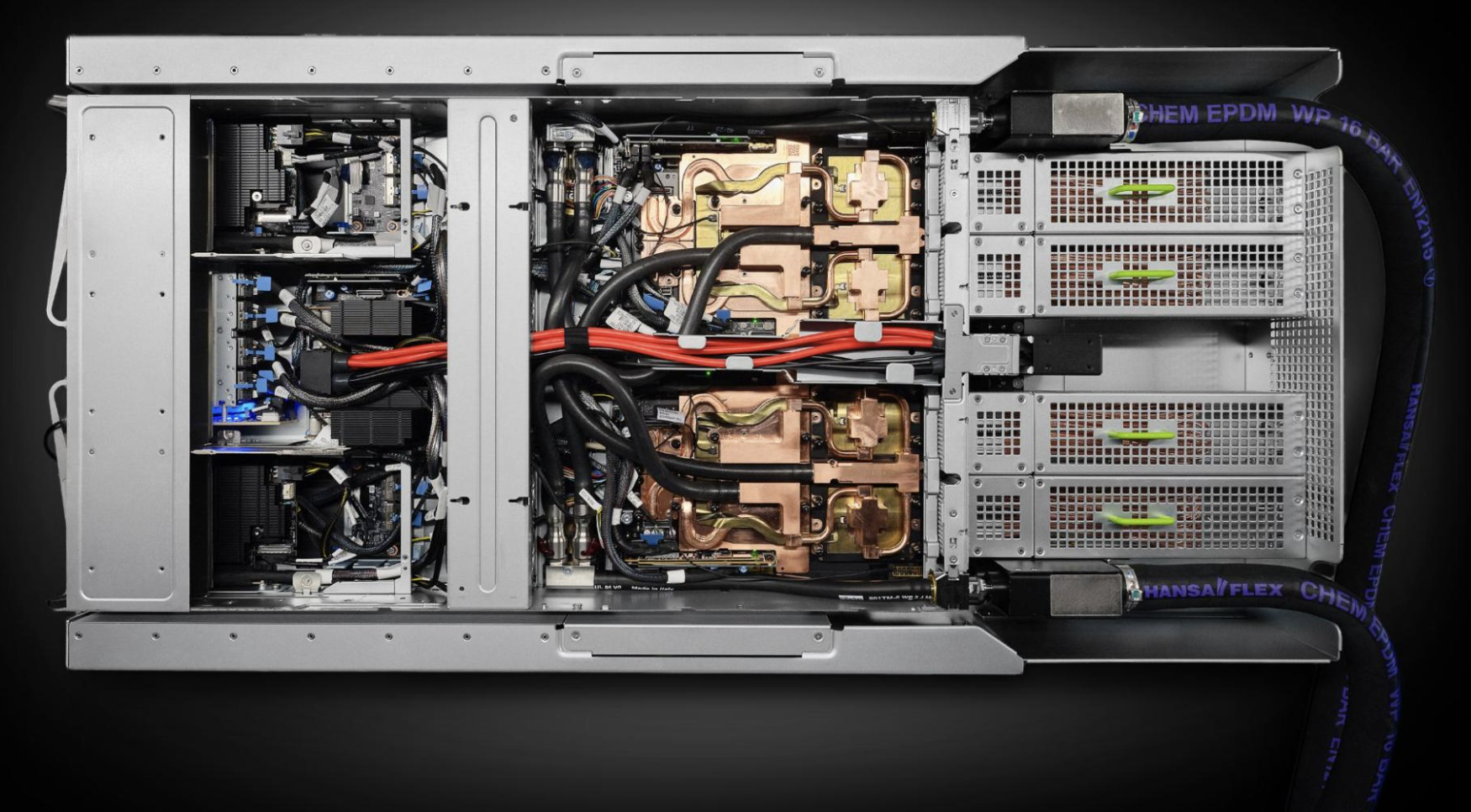
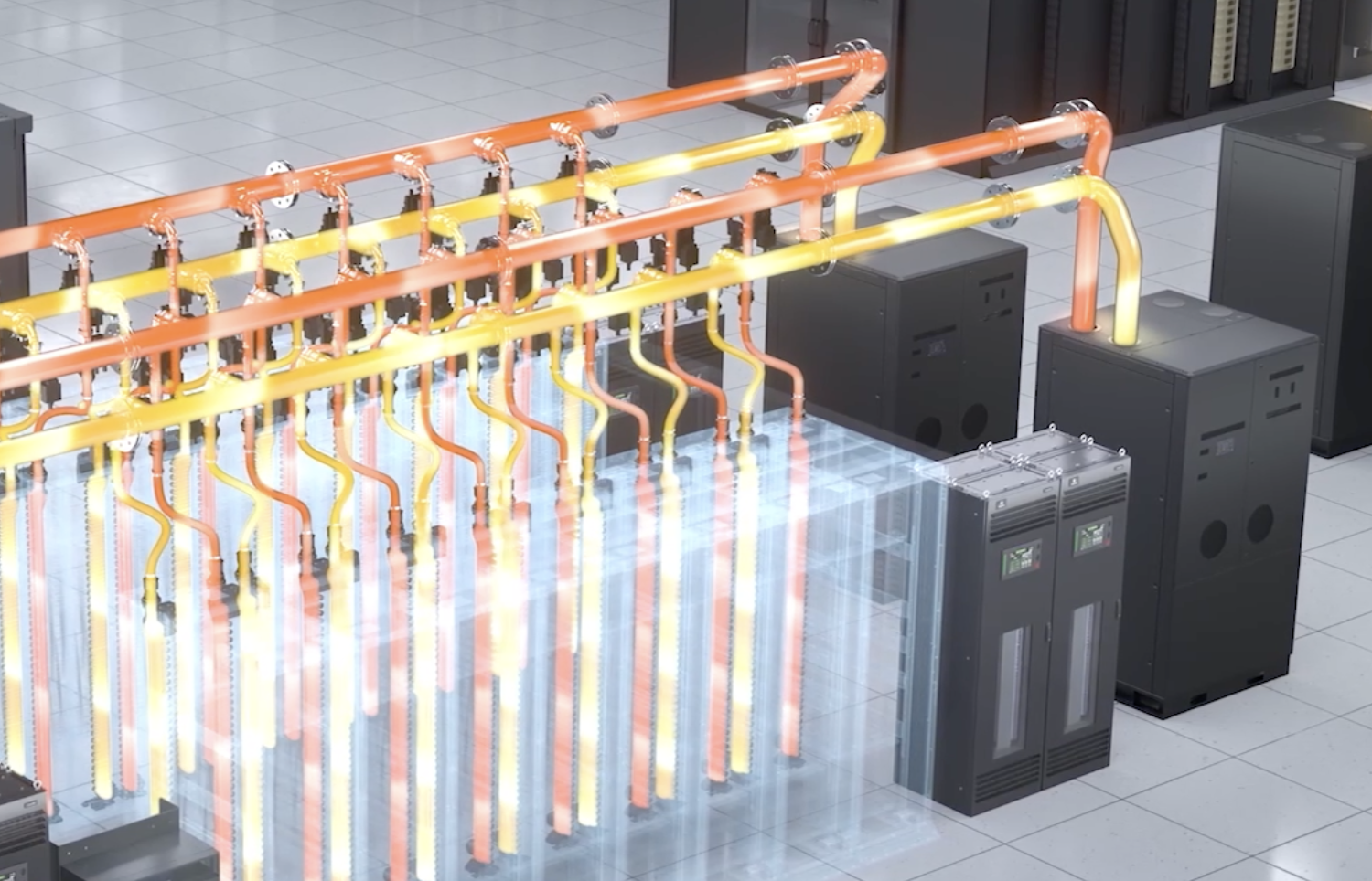
Selecting liquid cooling involves more than replacing an air-cooling system with a water loop. Direct-to-chip cooling creates a thermal and hydraulic path from the cold plate through the CDU and the facility water system to the final heat-rejection system. Each part of this path has defined temperature, pressure, water quality, control and isolation limits. These limits must be checked together when sizing and controlling the system.
The complete heat path
A typical direct-to-chip architecture begins with cold plates on GPUs and CPUs followed by server tubing, quick disconnects, rack manifolds, a technology cooling loop, a coolant distribution unit, a facility water loop, heat exchangers, pumps, and final heat rejection. Air remains necessary for components not captured by the liquid loop.
The heat not captured by the liquid cooling loop, referred to as the residual load, may come from memory, storage, power supplies, network equipment, and heat leakage from liquid-cooled components. Consequently, the data hall becomes a hybrid environment: liquid distribution handles most of the heat, while a smaller but still critical air-cooling system removes the remaining load.
Temperature is an architectural choice
Higher technology-coolant temperatures can expand economizer hours, reduce chiller dependence, and improve the feasibility of exporting useful heat. But the allowable temperature is set by an interacting chain: chip junction limits, cold-plate resistance, flow, coolant heat capacity, server control logic, CDU approach temperature, facility-water temperature, and local wet-bulb or dry-bulb conditions. A high temperature reduces thermal margin unless the cold plates, flow rates, CDU approach temperature, facility water conditions, and degraded operating states have been checked together.
Design teams should compare cooling towers, dry coolers, evaporative systems, chillers, and hybrid heat-rejection options through annual simulations rather than looking at design-day efficiency alone. The evaluation must also account for water availability, plume, freeze protection, air quality, heat reuse, and maintenance access, which may change the preferred solution.
Beyond direct-to-chip
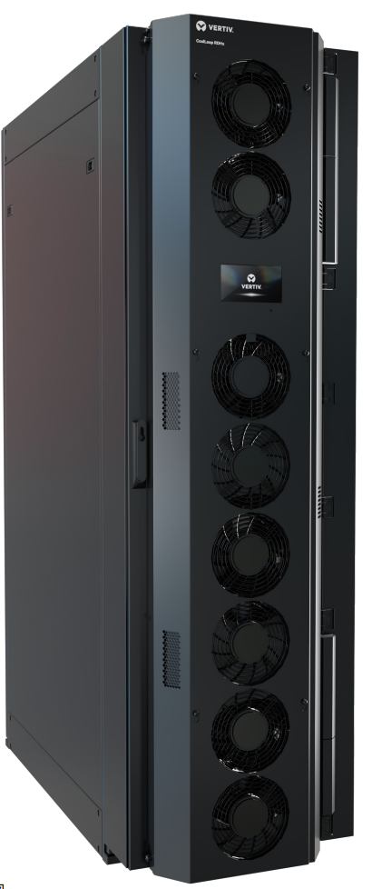
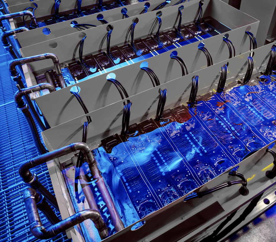
For retrofits and mixed-density halls, rear-door heat exchangers move heat removal closer to the rack without requiring server-level liquid interfaces. Rear-door heat exchangers remain valuable for retrofits and mixed-density halls because they move heat removal close to the rack without requiring server-level liquid interfaces. Immersion cooling offers high heat capture and compact density but changes hardware compatibility, dielectric-fluid management, service procedures, fire strategy, and supply-chain assumptions.
Direct-to-chip cooling currently has broader server and facility integration for rack-scale AI. Immersion cooling may suit specific platforms, but it requires compatible hardware, fluids, service procedures, and operating practices.
Match the interconnect to the cluster scale
Why does scaling change the network requirement
In a distributed AI cluster, GPU communication can consume a significant part of the training cycle, particularly during collective operations such as AllReduce and All-to-All. The larger the cluster, the more sensitive overall performance becomes to network latency, bandwidth, topology, and congestion.
InfiniBand vs. RoCE
InfiniBand is often favored for large, tightly coupled training clusters because it provides a purpose-built high-performance fabric with RDMA and low-latency communication. RoCE provides RDMA over Ethernet and can be attractive where existing Ethernet infrastructure, operational familiarity, interoperability, and TCO are important.
Cluster size alone does not determine the fabric. Workload communication patterns, performance consistency, existing network infrastructure, and operational capability are also part of the decision.
| InfiniBand | RoCE | |
| Fabric | Dedicated high-performance fabric | Ethernet-based |
| Best fit | Large, tightly coupled training | Mid-scale / mixed workloads |
| Key advantage | Predictable AI/HPC communication | Ethernet ecosystem and flexibility |
| Key consideration | Specialized infrastructure | Careful congestion management |
Coordinate cable pathways with other facility services
For large AI deployments, the network topology must be defined early enough to inform rack layout, switch placement, fiber routes, cable reach, and network-rack power requirements.
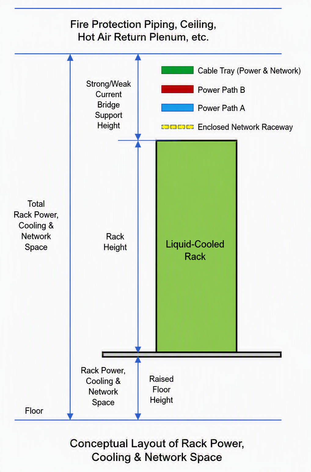
A coordinated room section separates liquid piping, power distribution, fiber trays, fire protection, and maintenance access into defined vertical zones. Large pipes follow structurally suitable routes with access to support, valves, and drains, while protected fiber routes use controlled crossing. The layout also preserves access to power tap-offs and isolation points without obstructing fire-protection coverage or detector sightlines.
Size pods around failure and maintenance domains
The physical pod should reflect the same boundaries used by the compute, power, network, and cooling system. Aligning these domains contains the impact of a fault and allows teams to maintain one part of the infrastructure without unnecessarily affecting adjacent capacity. The following sections explain how to map reliability requirements and isolation measures to these pod boundaries.
Align reliability with compute and cooling domains
Traditional resilience planning often begins with A-side/B-side power, UPS, and redundant feeders. An AI cluster also depends on cooling, network, and control system. A training cluster can lose useful compute capacity due to power interruptions, coolant degradation, network partitions, control-system failures, thermal throttling, or maintenance activities that unintentionally affect multiple systems.
Reliability analysis should measure how each credible failure affects usable compute capacity and how the workload recovers instead of assessing equipment redundancy in isolation. Electrical blocks, CDU branches, network fabrics, and control zones should be mapped to rack and pod boundaries so that a single credible fault does not disable an unacceptable portion of the compute cluster.
Segment for isolation, not indiscriminate redundancy
Apply redundancy where it limits lost compute capacity or keeps the rest of a pod available during maintenance. For example, sectionalized cooling branches can isolate a leaking rack without draining the entire pod, while segmented busways and diverse fabric path can obtain electrical and network faults. Shared systems also need defined bypass and restoration sequences that avoid common-mode failures.
Liquid cooling introduces additional failure scenarios and time scales. A pump trip may be tolerable if redundant pumping starts quickly and the system has sufficient thermal inertia. A contamination event may develop slowly and affect multiple cold plates before it is detected, while a small leak can become a major operational event if isolation requires draining an entire pod.
Each failure scenario should define how the condition is detected, what the control system does automatically, when operators intervene, and what conditions must be met before service is restored. The analysis should cover both sudden failures and gradual degradation.
Use modularity and standardization to enable repeatable growth
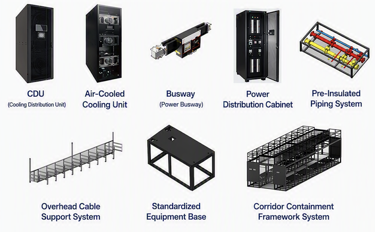
Modular construction can shorten deployment time, but its longer-term value lies in the ability to replace compute modules without rebuilding the broader electrical and cooling infrastructure. Compute generations may change during design or construction, while transformers, switchgear, cooling equipment, and buildings remain in service for decades. A repeatable pod separates short-life compute and network equipment from longer-life assets such as transformers, switchgear, piping, and heat-rejection systems.
Define standardized pod interface
A useful pod definition includes compute and network capacity, input-power architecture, cooling duty and temperatures, physical envelope, controls, isolation, test points and operational responsibility. It may be delivered as prefabricated power rooms, hydraulic skids, structural modules or conventional construction.
The pod specification should allow a range of rack power densities, coolant conditions, and network configurations because compute platforms change faster than permanent electrical and mechanical infrastructure. Defining capacity bands and replaceable interface modules allows the pod to support later hardware without redesigning the entire facility. The design basis should classify components by expected service life and define whether each component can be replaced with the pod isolated or while adjacent pods remain in service.
Build control, monitoring, and digital visibility for operation
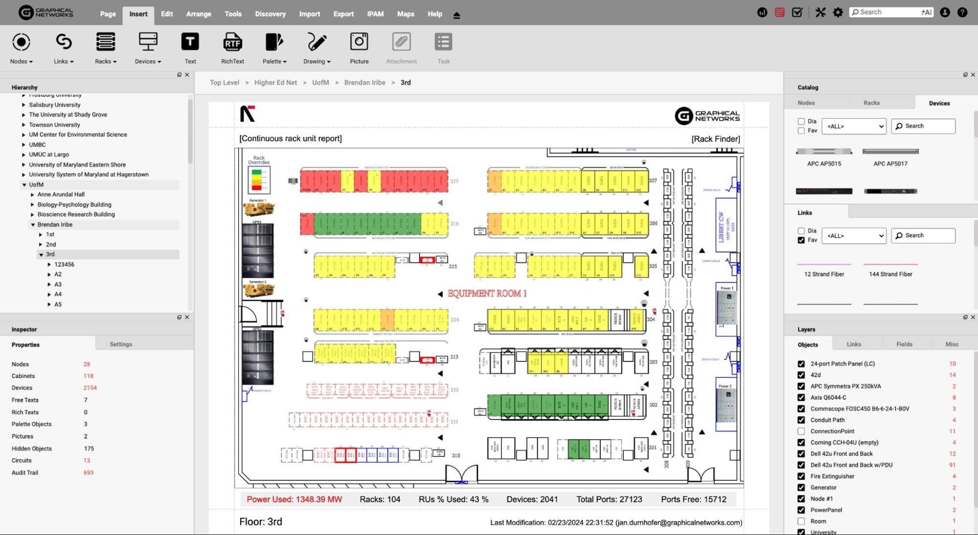
AI data centers require operational visibility across facility systems, advanced cooling, IT equipment, and network infrastructure. Monitoring these systems independently creates fragmented data and makes it difficult to understand how an infrastructure event affects compute availability. A common data model should, therefore, connect telemetry from power, cooling, racks, GPUs, and network equipment into a consistent operational view.
From telemetry to actionable operations
Additional telemetry is useful only when operators can relate it to equipment condition. Operators should be able to trace a facility alarm to the affected CDU, rack, network segment, and compute availability. For example, a rising coolant temperature should be traceable from the facility water loop to the CDU, rack, and affected GPUs, while a network or power event should be correlated with the compute capacity that may be lost.
Dashboards should show the measurements needed for a response, including rack power, coolant supply, and return temperature, flow, thermal margin, network status, and active alarm.
Infrastructure clarity for organizations across all industries
Conclusion
Design teams must treat rising compute density, power demand, advanced cooling requirements, and network traffic as one integrated infrastructure problem. They should start with workload and platform requirements, translate them into coordinated power, cooling, and network architectures, align those architectures with failures and maintenance domains, and standardize the resulting pods for repeatable deployment and operation.
The design principles in this article can be summarized as follows:
- Design for modularity: Use standardized racks and pods as repeatable capacity blocks. Modular architectures enable phased deployment and predictable expansion without overbuilding the entire facility.
- Design power and cooling together: Treat electrical capacity and heat rejection as coupled constraints. High-density AI racks require coordinated design of power distribution, liquid cooling, residual air cooling, and supporting infrastructure rather than independent electrical and mechanical sizing.
- Match the interconnect to the cluster: Select InfiniBand, RoCE, NVLink, or other interconnect technologies based on cluster scale, communication patterns, performance requirements, and operational constraints. Network topology should be considered a facility design input because it affects rack placement, fiber pathways, power, and expansion capacity.
- Design around failure and maintenance domains: Size pods and infrastructure boundaries to contain credible failures and support maintenance without unnecessarily taking large portions of the cluster offline. Reliability should account for power, cooling, network, controls, and workload behavior together.
- Build for operational visibility: Connect facility, liquid cooling, IT, and network telemetry through consistent data models. Link facility and IT alarms to the affected racks, GPUs, and network segments so that operators can identify the required response.
These best practices give project teams a repeatable way to translate change compute requirements into infrastructure decisions. Standardized interfaces, bounded failure domains, and cross-system visibility also help the facility absorb later hardware generations without sacrificing safe and maintainable operation.
